System method and device for leak detection and localization in a pipe network

Active Publication Date: 2012-01-12
AQUARIUS SPECTRUM
View PDF30 Cites 114 Cited by
  • Summary
  • Abstract
  • Description
  • Claims
  • Application Information

AI Technical Summary

Benefits of technology

[0008]In a second aspect, the invention provides a method for processing signals generated by the flow meters and vibration detects for detection and location of leaks in the pipe network. In accordance with this aspect of the invention, the processing uses flow data obtained from the flow meters to redu

Problems solved by technology

However, the AMR systems cannot detect leaks in pipes that are below their measurement threshold.
AMR systems also cannot detect leaks that are less than 1% of the nominal flow in the distribution pipes nor locate the leak as the mass balance is done over a relatively large pipe network.
Correlation analysis requires synchronization of the clocks of the

Method used


Image

  • System method and device for leak detection and localization in a pipe network
  • System method and device for leak detection and localization in a pipe network
  • System method and device for leak detection and localization in a pipe network

Examples


Embodiment Construction

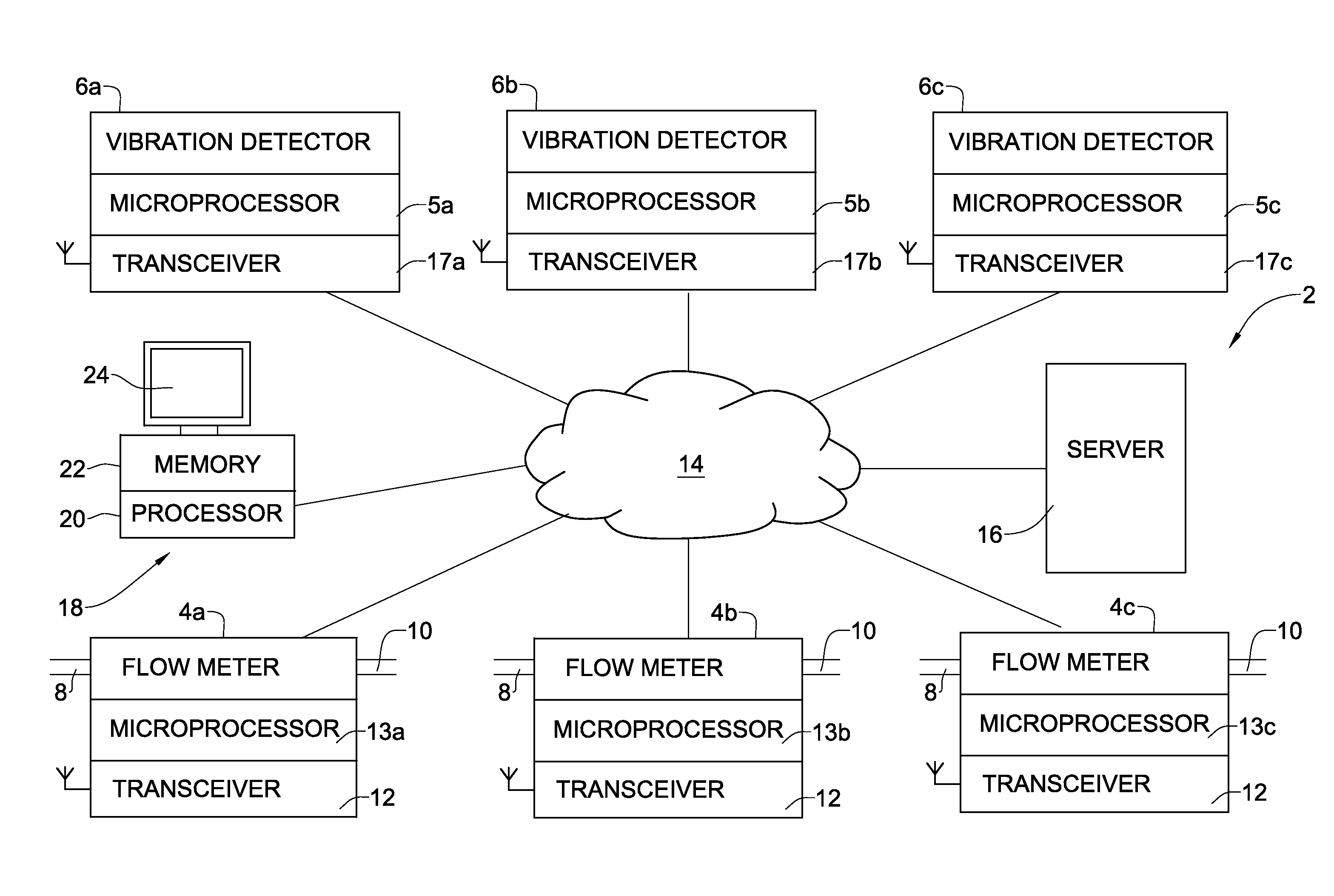
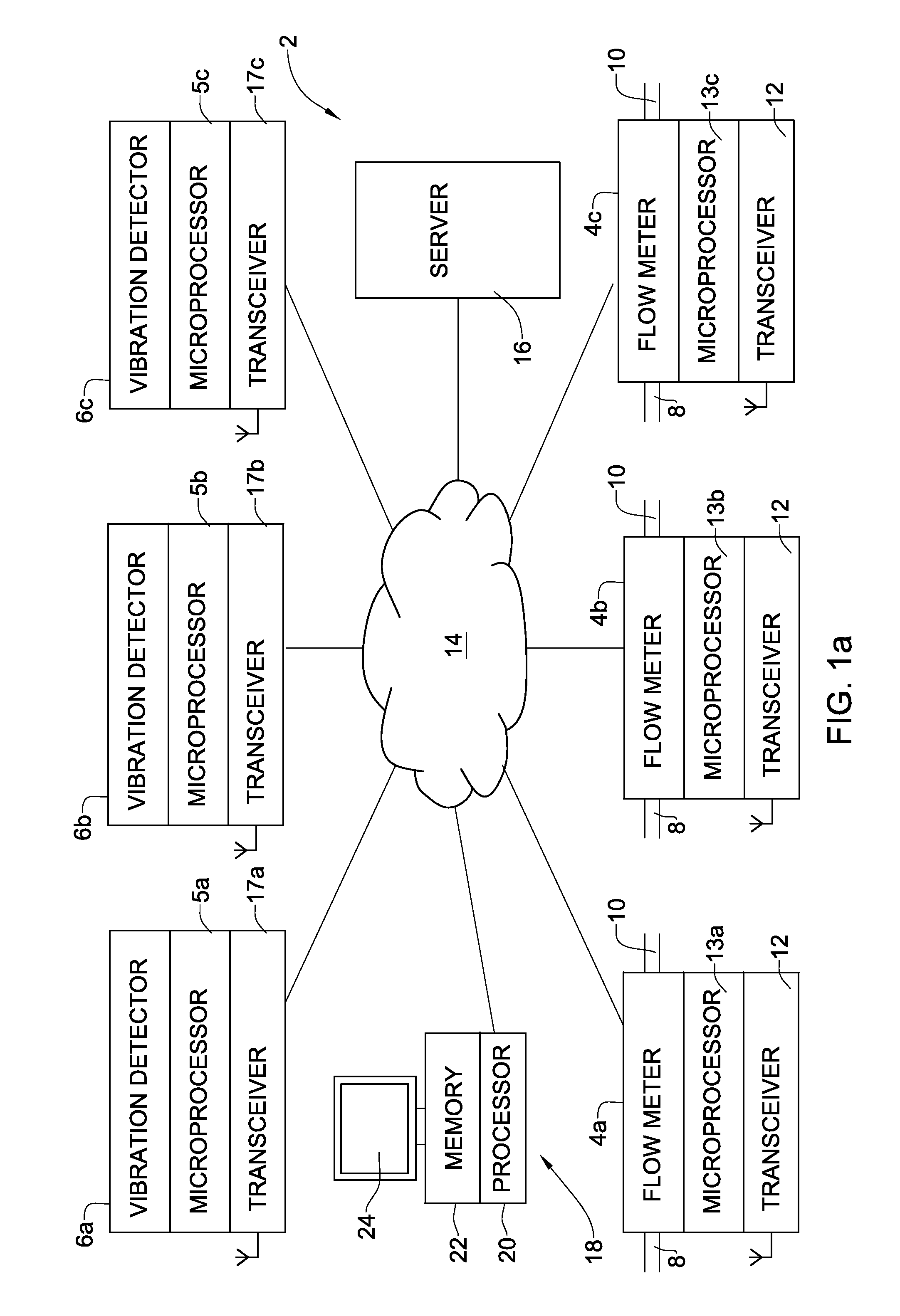
[0037]FIG. 1a shows a system 2 for leak detection in a pipe network, in accordance with one embodiment of this aspect of the invention. The system 2 comprises two or more flow meters 4 and a plurality of vibration detectors 6. Three flow meters 4a, 4b, and 4c, and three vibration detectors 6a, 6b, and 6c, are shown in FIG. 1. This is by way of example only, and the system of the invention may be implemented using any number of flow meters that is at least two, and any number of vibration detectors that is at least two. The number of flow meters may be less than, equal to or greater than the number of vibration detectors. The flow meters may be any flow meter known in the art. Each flow meter has a flow inlet 8 and a flow outlet 10 that allows the flow meter to be installed on a flow line at a location in the pipe network. The vibration meters 6 may be any type of vibration detector known in the art, such as an accelerometer, strain-gage or hydrophone type sensor. The hydrophone tend...


PUM


Abstract

The invention provides a system for leak detection of a fluid in a pipe network. The system includes flow meters, and vibration detectors adapted to be attached to a pipe at a location in the pipe network. A processor analyzes signals generated by the flow meters and vibration detectors to identify the presence of one or more leaks in the pipe network. The invention also provides a method for detecting and localizing leaks in a pipeline network, and a device comprising a flow meter integral with a vibration detector for use in the system of the invention.

Description

FIELD OF THE INVENTION[0001]This invention relates to systems, methods and devices for leak detection.BACKGROUND OF THE INVENTION[0002]Electronic automatic meter reading (AMR) devices are used for flow metering in a pipeline. These devices typically use an electronic unit attached to a conventional magneto-mechanical or electronic flow meter, for example as disclosed in U.S. Pat. Nos. 4,940,976 and 6,611,769. Magneto-mechanical flow meters typically measure integrative water consumption by means of a mechanical gear. The accumulated liquid consumption is read by opto-electronic circuits, or by piezo-electric pick up of the gear rotation, which are usually packed in a dry section-register. In electronic meters, a magnetic sensor monitors the liquid meter rotor revolutions and generates an electrical signal indicative of the water flow. The sensor may be based, for example, on an inductive coil, a Hall effect sensor, or a magnetoresistive device. Some devices use optical pick-up syste...

Claims


Application Information

Patent Timeline
IPC IPC(8): G08B21/00G01M3/00
CPCG01M3/243G01N29/14G01M3/24G01M3/2807G01F1/66
Inventor SOLOMON, DAVID
Owner AQUARIUS SPECTRUM
Why Eureka
Try Eureka