
Liquid crystal display device, process for producing liquid crystal display device, composition for forming polymer layer, and composition for forming liquid crystal layer

a liquid crystal display and composition technology, applied in the direction of metallic material coating process, synthetic resin layered products, pretreatment surfaces, etc., can solve the problems of image sticking and the likelihood of changing the pretilt angle, so as to prevent image sticking and prevent image sticking

Inactive Publication Date: 2012-01-12
SHARP KK
View PDF2 Cites 25 Cited by
  • Summary
  • Abstract
  • Description
  • Claims
  • Application Information

AI Technical Summary

Benefits of technology

[0049]Since the liquid crystal display device of the present invention includes a polymer layer made of a polymer that contains monomer units of at least two species of monomers, on an alignment film, the liquid crystal display device of the present invention can achieve both of a benefit of preventing image sticking caused by a change in the pretilt angle and benefit of preventing image sticking caused by a residual DC voltage.

Problems solved by technology

However, even liquid crystal display devices including an alignment film produced by the PSA technology often have image sticking in their liquid crystal displays.
Possible main causes of image sticking are as follows: pretilt angles are likely to be changed due to light emitted from a backlight or an applied AC voltage in the case where the binding force between monomer units in a polymer layer (hereinafter, also referred to as a PSA layer) produced by the PSA technology is not enough; and a residual DC voltage is generated in the alignment film and the PSA layer due to inpurities attached on the PEA layer or low resistance of the PSA layer.

Method used


Image

  • Liquid crystal display device, process for producing liquid crystal display device, composition for forming polymer layer, and composition for forming liquid crystal layer
  • Liquid crystal display device, process for producing liquid crystal display device, composition for forming polymer layer, and composition for forming liquid crystal layer
  • Liquid crystal display device, process for producing liquid crystal display device, composition for forming polymer layer, and composition for forming liquid crystal layer

Examples


first embodiment

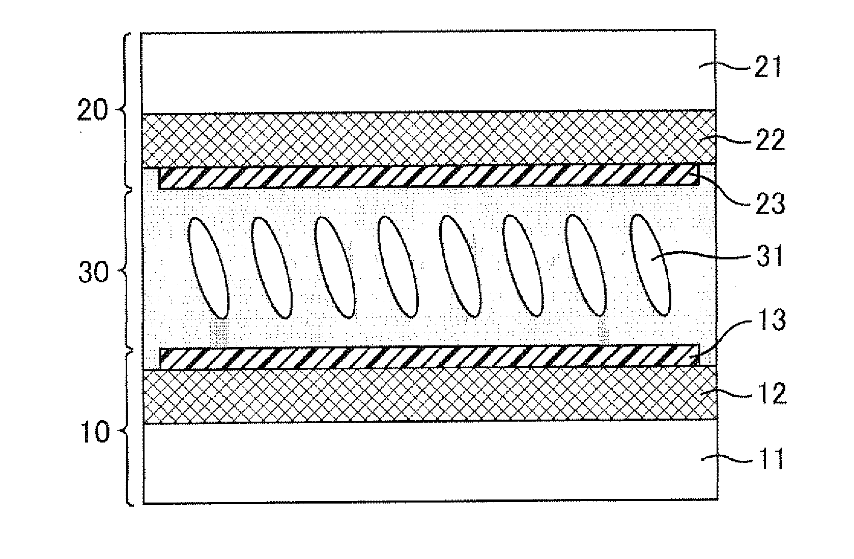
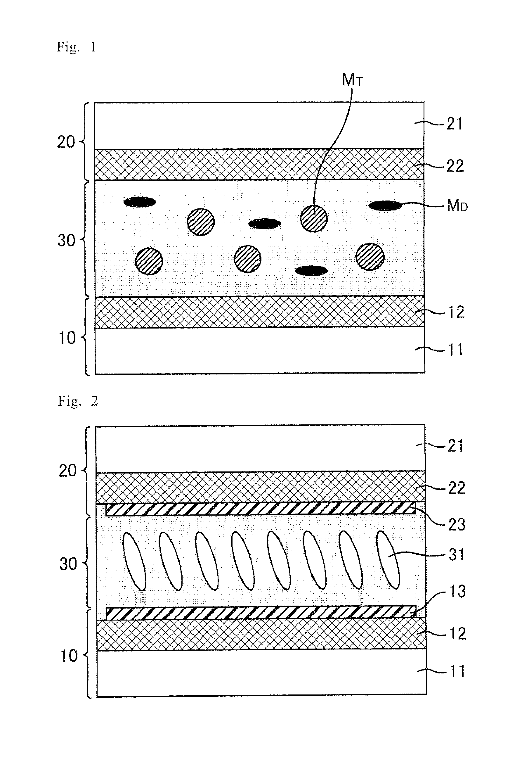
[0055]FIGS. 1 and 2 are schematic cross-sectional views of a liquid crystal display device according to the first embodiment. FIG. 1 shows the device before a PSA polymerization step and FIG. 2 shows the device after the PSA polymerization step. As shown in FIGS. 1 and 2, the liquid crystal display device according to the first embodiment includes a pair of substrates (i.e. an array substrate 10 and a color filter substrate 20), a liquid crystal layer 30 between the array substrate 10 and the color filter substrate 20. The array substrate 10 includes a supporting substrate 11 which includes an insulating transparent substrate such as a glass substrate, lines of various types, pixel electrodes, TFTs, and the like on the transparent substrate. The color filter substrate 20 includes a supporting substrate 21 which includes an insulating transparent substrate such as a glass substrate, color filters, a black matrix, a common electrode, and the like on the transparent substrate.

[0056]The...

example 1

[0084]Hereinafter, Example 1 is described in which a liquid crystal cell of the liquid crystal display device according to the first embodiment was actually produced. First, as a vertical alignment film material, a solution containing a polyamic acid or polyimide including a side chain containing a photoactive functional group was applied to the surfaces of a pair of supporting substrates. The substrates were pre-baked at 80° C. and then post-baked at 200° C. for 60 minutes

[0085]Next, a photo-alignment treatment was performed by emitting polarized UV rays with a wavelength of about 300 nm from a direction oblique at 45° to the surfaces of the supporting substrates. The dose of UV rays was 100 mJ / cm2.

[0086]Next, a seal was applied to one of the supporting substrates and beads were scattered on the other supporting substrate. The supporting substrates were attached to each other, and a composition for a liquid crystal layer which contains a liquid crystal material having negative diel...

example 2

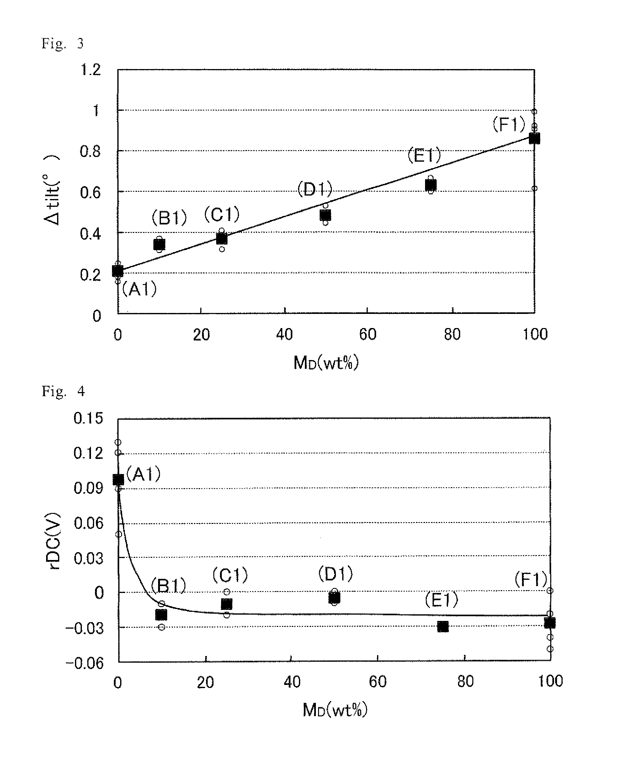
[0097]Hereinafter, Example 2 is described in which a liquid crystal cell of the liquid crystal display device according to the first embodiment was actually produced. In Example 2, samples were prepared in the same manner as in Example 1, except that a different polymerizable monomer MT (monomer for reducing pretilt image sticking) and a different polymerizable monomer MD (monomer for reducing DC image sticking) were used. The polymerizable monomer MT and the polymerizable monomer MD used in Example 2 were a compound represented by the following formula (13) and a compound represented by the following formula (14), respectively.

[0098]The weight ratios (MT:MD) of the polymerizable monomer MD to the polymerizable monomer MD of the samples prepared in Example 2 were 9:1 (sample B2), 3:1 (sample C2), 1:1 (sample D2), and 1:3 (sample E2). Further, for preparation of reference cells for comparison with the samples used in the present example, a composition containing only the polymerizabl...


PUM

PropertyMeasurementUnit
weight ratioaaaaaaaaaa
pretilt angleaaaaaaaaaa
wavelengthaaaaaaaaaa

Abstract

The present invention provides a liquid crystal display device capable of reducing the probability of image sticking. The liquid crystal display device includes a pair of substrates and a liquid crystal layer between the substrates. At least one of the substrates includes an alignment film and a polymer layer on the alignment film. The polymer layer includes monomer units derived from at least two species of polymerizable monomers. The at least two species of polymerizable monomers include at least two species of monomers selected from the group consisting of: specific polyfunctional monomers and specific monofunctional monomers.

Description

TECHNICAL FIELD[0001]The present invention relates to a liquid crystal display device, a method for producing a liquid crystal display device, a composition for a polymer layer, and a composition for a liquid crystal layer. More specifically, the present invention relates to a liquid crystal display device having a polymer layer formed on an alignment film; a method for producing a liquid crystal display device which includes the steps of forming a resin film and forming a polymer layer on this alignment film; a composition for a polymer layer which is suitable for polymer layer formation; and a composition for a liquid crystal layer which is suitable for polymer layer formation.BACKGROUND ART[0002]Liquid crystal displays (LCDs) are display devices that control transmission / reflection of light (ON / OFF of display) by controlling the alignment of birefringent liquid crystal molecules. One way to align liquid crystal molecules is to adopt a structure in which an alignment film subjecte...

Claims


Application Information

Patent Timeline
Patent Type & Authority Applications(United States)
IPC IPC(8): G02F1/1337B05D3/14C08F222/18B05D3/00C09K19/56C08F222/14B05D5/06B05D3/06
CPCG02F1/133788C08F220/30G02F2001/133715C08F220/02B32B27/34C08F222/1006Y10T428/10Y10T428/1005G02F1/133723G02F2001/133397Y10T428/1023B32B27/281B32B27/308B32B2307/308B32B2307/412B32B2307/75B32B2457/202C08F222/1025C09K2323/00C09K2323/02C09K2323/027G02F1/133397G02F1/133715
Inventor MIZUSAKI, MASANOBUKATAYAMA, TAKASHIKAWAHIRA, YUICHINOMA, TAKESHINAKANISHI, YOHEI
Owner SHARP KK
Learn More