Char-handling processes in a pyrolysis system

a pyrolysis system and char-handling technology, applied in the direction of combustible gas purification/modification, lighting and heating apparatus, combustion types, etc., can solve the disadvantage of pyrolysis biomass, large quantities of excess dilution air or the addition of expensive cooling systems,

Active Publication Date: 2012-01-19
ENSYN RENEWABLES
View PDF29 Cites 39 Cited by
  • Summary
  • Abstract
  • Description
  • Claims
  • Application Information

AI Technical Summary

Benefits of technology

[0010]Processes are provided for controlling heat balance, afterburn, and ash accumulation in a reheater in accordance with yet another exemplary embodiment of the present invention. The process comprises separating spent heat transfer medium from a pyrolysis reactor into char-depleted spent heat transfer medium and segregated char. The char-depleted spent heat transfer medium is introduced into a fluidized dense bed of heat transfer medium. The fluidized dense bed is maintained by a stream of oxygen-containing regeneration gas and a dilute phase above the fluidized dense bed. At least a portion of the segregated char is introduced into the fluidized dense bed of the reheater below the elevation where the char-depleted spent heat transfer medium is introduced, into the stream of oxygen-containing regeneration gas outside of the reheater, or both, to combust the segregated char below the dilute phase.
[0011]Processes are provided for controlling heat balance, afterburn, and ash accumulation in a reheater

Problems solved by technology

Heat is transferred from the reheater to the pyrolysis reactor by a “heat transfer medium.” While the heat for the endothermic pyrolysis reaction and ambient heat losses (collectively “heat demand”) are normally balanced with the heat supplied from combustion in the reheater, heat balance is not always achieved.
If too much heat is generated, large quantities of excess dilution air or the addition of expensive cooling systems may be required for the pyrolysis system.
When the regenerated heat transfer medium is recirculated to the pyrolysis reactor with ash present, pyrolysis of the biomass may be disadvantageously affected by increased gas production.
The short heigh

Method used


Image

  • Char-handling processes in a pyrolysis system
  • Char-handling processes in a pyrolysis system
  • Char-handling processes in a pyrolysis system

Examples


Embodiment Construction

[0019]The following detailed description of the invention is merely exemplary in nature and is not intended to limit the invention or the application and uses of the invention. Furthermore, there is no intention to be bound by any theory presented in the preceding background of the invention or the following detailed description of the invention.

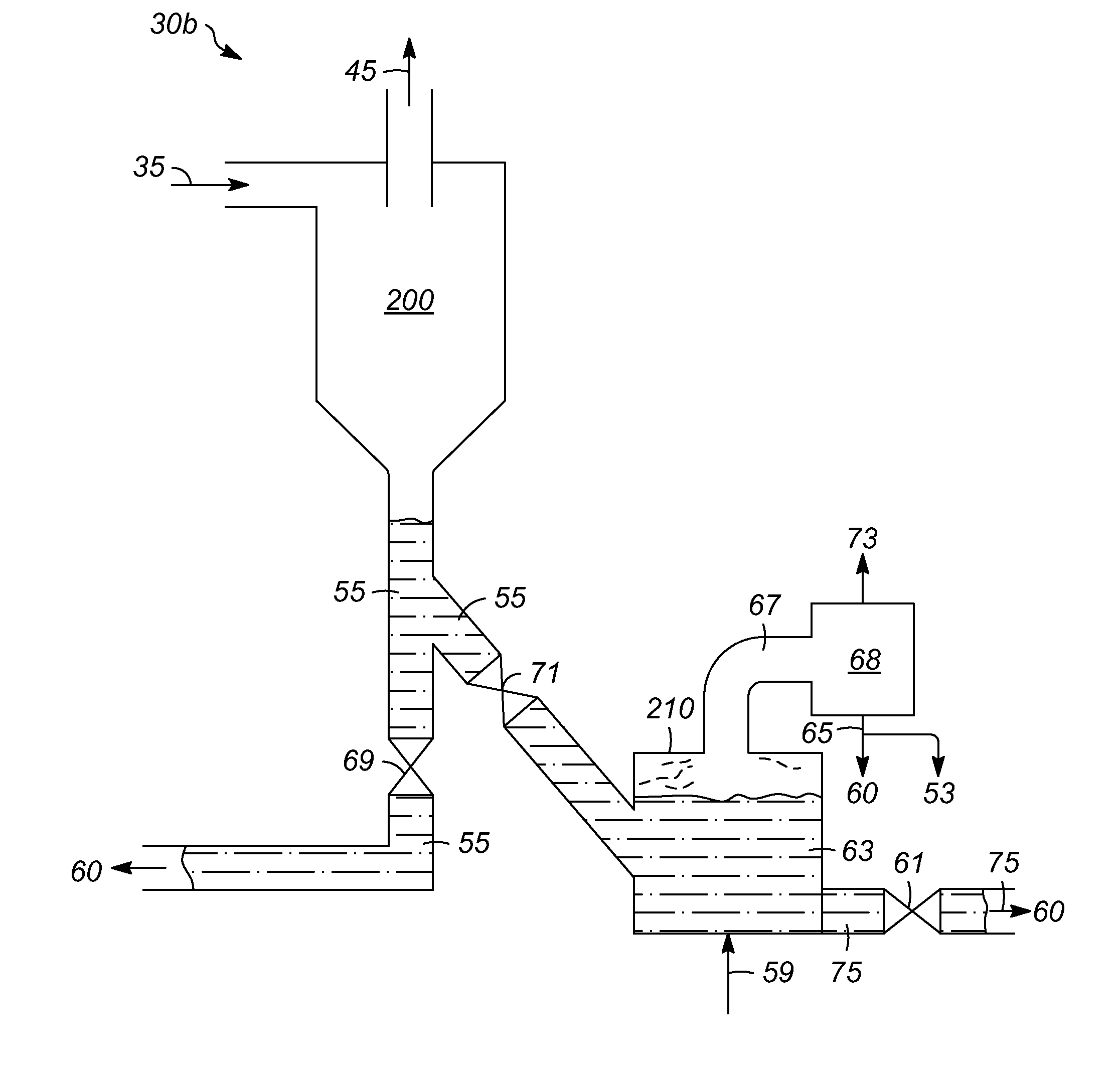
[0020]Various exemplary embodiments of the present invention are directed to processes for handling combustible solids (hereinafter “combustible solids” or “char” produced during pyrolysis of carbonaceous biomass feedstock). Char is segregated from a heat transfer medium to control afterburn in a reheater during regeneration of the heat transfer medium. A portion of the segregated char may be exported to control the overall heat balance and accumulation of ash in the pyrolysis system.

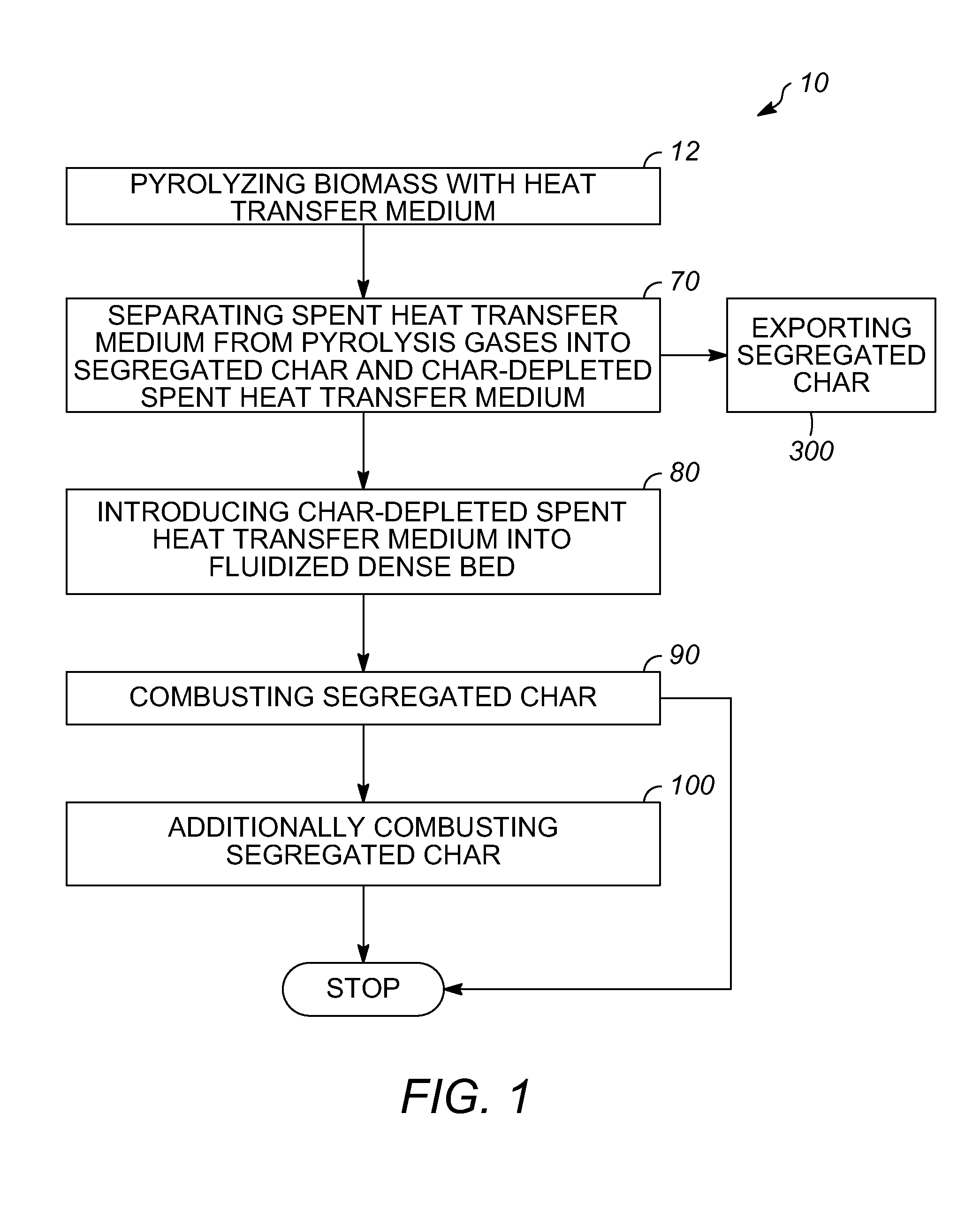
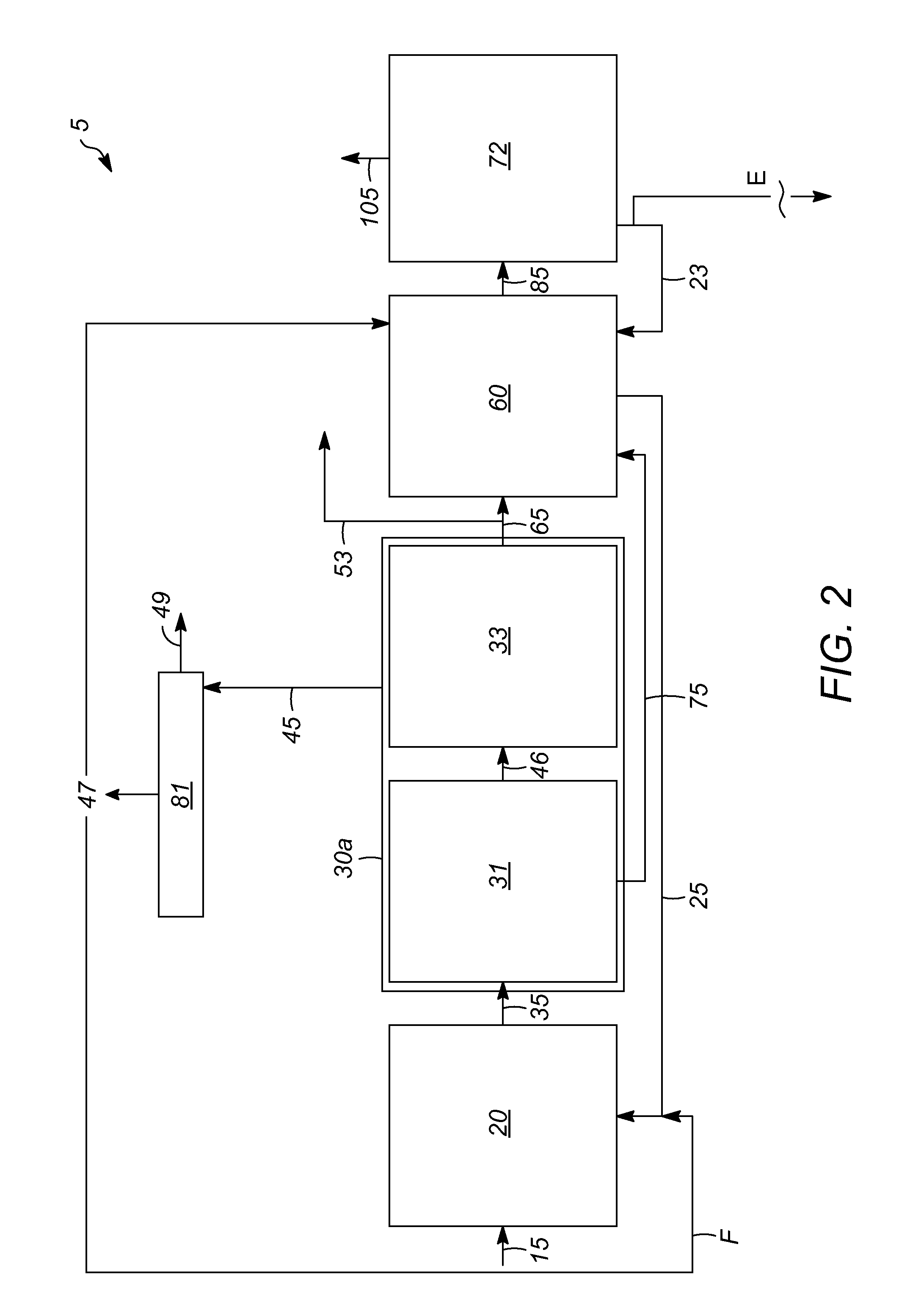
[0021]FIG. 1 is a flow chart of a char-handling process 10, in accordance with an exemplary embodiment of the present invention. FIG. 2 illustrates a pyrolysis ...


PUM


Abstract

Char-handling processes for controlling overall heat balance, ash accumulation, and afterburn in a reheater are provided. Carbonaceous biomass feedstock is pyrolyzed using a heat transfer medium forming pyrolysis products and a spent heat transfer medium. The spent heat transfer medium is separated into segregated char and char-depleted spent heat transfer medium. The char-depleted spent heat transfer medium is introduced into a dense bed of heat transfer medium fluidized by a stream of oxygen-containing regeneration gas. All or a portion of the segregated char is combusted in the dense bed using the stream of oxygen-containing regeneration gas. A portion of the segregated char may be exported out of the pyrolysis system to control the overall heat balance and ash accumulation.

Description

FIELD OF THE INVENTION[0001]The present invention generally relates to char-handling processes in a pyrolysis system, and more particularly relates to char-handling processes for controlling the overall heat balance, ash accumulation, and afterburn in a reheater of a pyrolysis system.DESCRIPTION OF RELATED ART[0002]Pyrolysis is a thermal process during which solid carbonaceous biomass feedstock, i.e., “biomass”, such as wood, agricultural wastes / residues, algae, forestry byproducts, cellulose and lignin, municipal waste, construction / demolition debris, or the like, is rapidly heated to pyrolysis temperatures of about 300° C. to about 900° C. in the absence of air using a pyrolysis reactor. Biomass may be pyrolyzed using various pyrolysis methods, including the Rapid Thermal Process method and catalytic pyrolysis. Under these conditions, solid and gaseous pyrolysis products are formed. The gaseous pyrolysis products (“pyrolysis gases”) comprise a non-condensable portion and a condens...

Claims


Application Information

Patent Timeline
IPC IPC(8): F23G5/027F23G7/00
CPCC10B49/22C10B23/00C10C5/00C10K1/026F23G5/0273F23G5/30F23G5/46F23G5/50F23G7/10F23G2201/303F23G2201/304F23G2201/601F23G2206/10F23G2900/50205Y02E50/14C10B53/02Y02P20/145Y02P30/20Y02E50/10Y02P20/133
Inventor PALMAS, PAOLOSECHRIST, PAUL ALVINMYERS, DANIEL N.KULPRATHIPANJA, SIDFREY, STANLEY JOSEPHFREEL, BARRY
Owner ENSYN RENEWABLES
Why Eureka
Try Eureka