Member for masking film, process for producing masking film using the same, and process for producing photosensitive resin printing plate

a technology of resin printing plate and masking film, which is applied in the direction of photomechanical treatment, microlithography exposure apparatus, instruments, etc., can solve the problems of poor resolution, complex operation, and inability to deal with large-sized masking films, and achieve uniform light transmittance, maintain abrasion resistance and adhesion, and excellent production stability of ultraviolet-shielding resin layer.

Active Publication Date: 2012-01-19
LINTEC CORP
View PDF5 Cites 12 Cited by
  • Summary
  • Abstract
  • Description
  • Claims
  • Application Information

AI Technical Summary

Benefits of technology

[0022]According to the present invention, the ultraviolet-shielding resin layer is a multilayer structure composed of two or more layers including a layer (A) having a high carbon black content and a layer (B) having a low carbon black content, and the layer (A) is provided on the base-film side of the ultraviolet-shielding resin layer and the layer (B) is provided on the printing-plate side of the ultraviolet-shielding resin layer. This makes it possible to obtain a member that is excellent in terms of the production stability of the ultraviolet-shielding resin layer while maintaining abrasion resistance and adhesion with the base film, and is suitable for the production of a masking film to be used in the production of a photosensitive resin printing plate or the like. Further, the member for masking films have the following advantages: areas at which the ultraviolet-shielding resin layer is removed accurately and precisely with a low-energy laser beam exhibit uniform light transmittance; the ultraviolet-shielding resin layer is resistant to scratches; further, the member for masking films provides a masking film which, in the production of a large-sized printing plate, allows easy positioning and is less likely to trap air when brought into close contact with the printing plate, so that the entire surface easily comes into close contact with a printing material; etc. The present invention also makes it possible to provide a process for producing a masking film using the same and a process for producing a photosensitive resin printing plate using the masking film.

Problems solved by technology

However, these methods cannot deal with large-sized masking films.
In addition, in a photographic method, although resolution is excellent, there are drawbacks in that the operation must be done in a special dark room, and, further, a number of chemical treatments are required, whereby the operation is complicated, for example.
However, in a printing method that uses a laser beam printer offered by XANTE (U.S.), there are drawbacks in that chemical treatments are required in order to increase the light-blacktop properties of a masking film, and also that the resolution is poor.
However, these techniques are techniques of producing a printing plate by irradiating a resin printing material directly with a laser beam rough no masking film, and are not techniques of producing a masking film.
However, because the ultraviolet-shielding resin layer is a single layer, the masking film is prone to defects, such as coating nonuniformity and pinholes, as well as scratches due to abrasion the resin layer surface, etc.
Thus, in areas whose color has been eliminated by a laser beam, such problems may directly appear as a irregularity in light transmittance, or pinhole areas may be exposed, which may make it impossible to accurately produce a printing plate.

Method used


Image

  • Member for masking film, process for producing masking film using the same, and process for producing photosensitive resin printing plate
  • Member for masking film, process for producing masking film using the same, and process for producing photosensitive resin printing plate

Examples


example 1

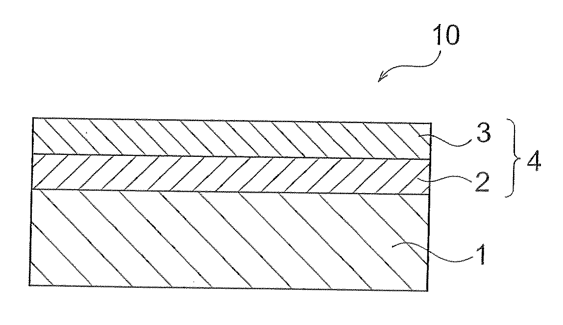
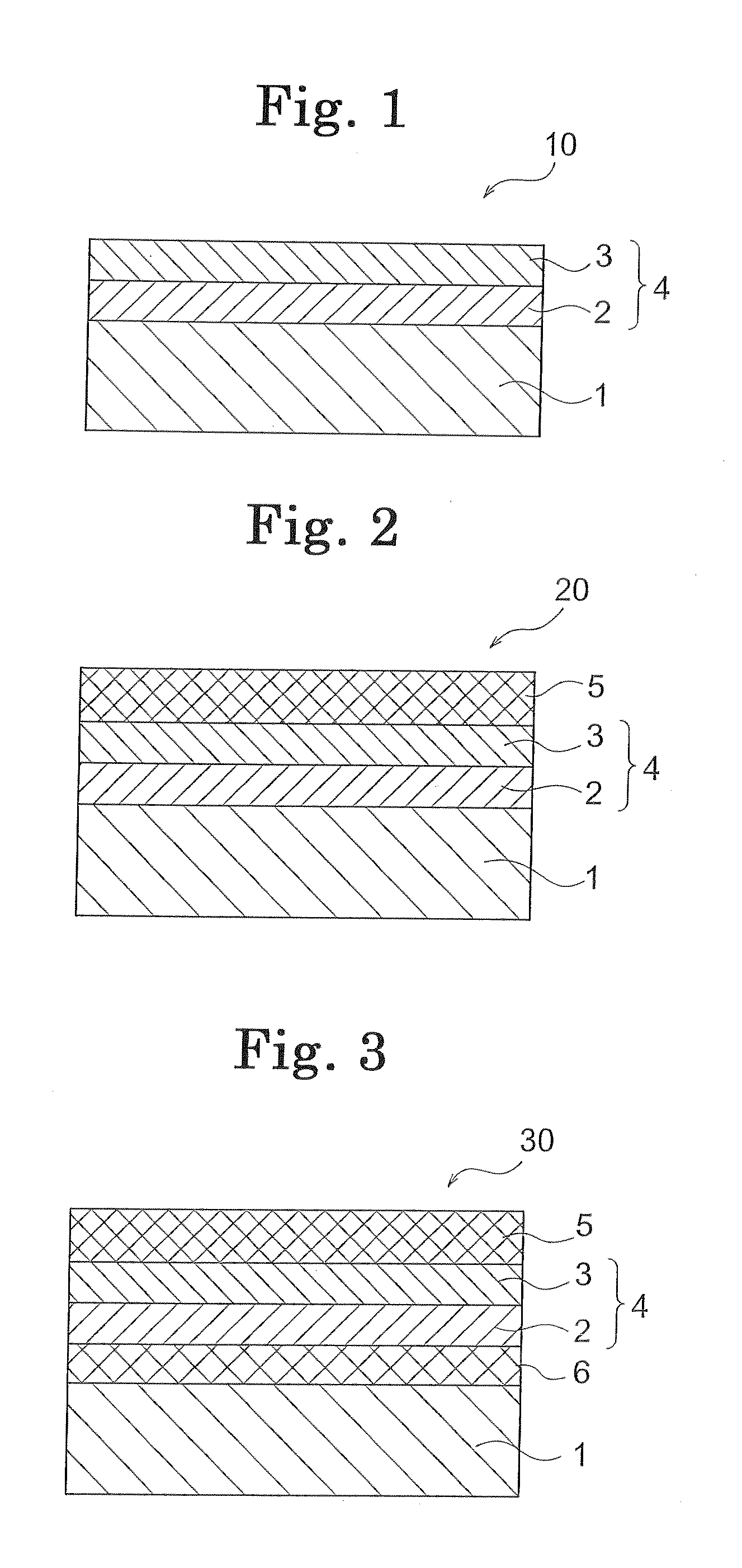
[0095]To one surface of a polyethylene terephthalate (PET) film having a thickness of 125 μm and a haze value of 0.95% [trade name “COSMOSHINE A4100”, manufactured by Toyobo Co., Ltd.], a carbon-black-containing resin liquid (A) [resin component: vinyl chloride / vinyl acetate copolymer having a Tg of not less than 40° C., carbon black average particle size: 24 nm, specific surface area: 115 g / m2, carbon black / resin content mass ratio: 1.61 / 1] was applied to an average dry thickness of 2.0 μm, followed by drying to form a layer (A). Then, onto the layer (A), a carbon-black-containing resin liquid (B) [resin component: vinyl chloride / vinyl acetate copolymer having a Tg of not less than 40° C., carbon black average particle size: 24 nm, specific surface area: 115 g / m2, carbon black / resin content mass ratio: 0.85 / 1, silica filler: 8 mass %] was applied to an average dry thickness of 0.5 μm, followed by drying to form a layer (B). An ultraviolet-shielding resin layer was thus formed, ther...

example 2

[0096]To one surface of a PET film having a thickness of 125 μm and a haze value of 0.95% (mentioned above), carbon-black-containing resin liquid (A) [resin component: acrylic resin having a Tg of not less than 40° C. with 32 mass % of a hexamethylene-diisocyanate (HDI)-based isocyanate crosslinking agent added thereto, carbon black average particle size: 24 nm, specific surface area: 115 g / m2, carbon black / resin content mass ratio: 1.36 / 1, silica filler added in an amount of 10 mass %] was applied to an average dry thickness of 2.0 μm, followed by drying to form a layer (A). Then, onto the layer (A), a carbon-black-containing resin liquid (B) [resin component: acrylic resin having a Tg of not less than 40° C. with 59 mass % of an HDI-based isocyanate crosslinking agent added thereto, carbon black average particle size: 24 nm, specific surface area: 115 q / m2, carbon black / resin content mass ratio: 0.83 / 1, silica filler: 8 mass % j was applied to an average dry thickness of 0.5 μM, f...

example 3

[0097]To one surface of a PET film having a thickness of 125 μm and a haze value of 0.95% (mentioned above), carbon-black-containing resin liquid (A) [resin component: acrylic resin having a Tg of not less than 40° C. with 32 mass % of an HDI-based isocyanate crosslinking agent added thereto, carbon black average particle size: 24 nm, specific surface area: 115 g / m2, carbon black / resin content mass ratio: 1.36 / 1, silica filler added in an amount of 10 mass %] was applied to an average dry thickness of 2.0 μm, followed by drying to form a layer (A). Then, onto the layer (A), carbon-black-containing resin liquid (B) [resin component: acrylic resin having a Tg of not less than 40° C. with 59 mass % of an HDI-based isocyanate crosslinking agent added thereto, carbon black average particle size: 24 nm, specific surface area: 115 g / m2, carbon black / resin content mass ratio: 0.83 / 1, silica filler: 8 mass %] was applied to an average dry thickness of 0.5 μm, followed by drying to form a lay...


PUM

PropertyMeasurementUnit
thicknessaaaaaaaaaa
wavelengthaaaaaaaaaa
ultraviolet transmittanceaaaaaaaaaa

Abstract

A member for masking films which includes a base film transparent to ultraviolet rays and, on one surface thereof, an ultraviolet-shielding resin layer capable of being removed by irradiation with laser light beams and having an average thickness of 0.1 to 30 μm, wherein the ultraviolet-shielding resin layer is a multilayer structure composed of two or more layers including a resin layer (A) having a high carbon black content and a resin layer (B) having a low carbon black content, the layer (A) and the layer (B) being located on the base-film side and on the printing-plate side of ultraviolet-shielding resin layer, respectively, and the ultraviolet-shielding resin layer has specific optical properties. This member for masking films has the following features: the accurate and precise removal of the ultraviolet-shielding resin layer using a low-energy laser beam gives areas with uniform light transmittance; the ultraviolet-shielding resin is resistant to scratches; and positioning is easy, and when making close contact with a plate, air trapping is less likely to occur so that the entire surface easily comes into close contact with a printing material.

Description

TECHNICAL FIELD[0001]The present invention relates to a member for masking films, a process for producing a masking film using the same, and a process for producing a photosensitive resin printing plate. More specifically, the present invention relates to a member for masking films, which is a member suitable for the production of a masking film to be used in the production of photosensitive resin printing plates such as flexographic printing plates and letterpress printing plates and the like, and wherein areas at which an ultraviolet-shielding resin layer is removed with a laser beam exhibit uniform light transmittance, and the ultraviolet-shielding resin layer is resistant to scratches. Further, the member for masking films provides a masking film which, in the production of a large-sized printing plate, allows easy positioning and less likely to trap air when brought into close contact with the plate, so that the entire surface easily comes into close contact with a printing mat...

Claims


Application Information

Patent Timeline
Patent Type & Authority Applications(United States)
IPC IPC(8): G03F7/20G03F1/00G03F1/56G03F7/00
CPCG03F1/68G03F7/20G03F7/202G03F1/56G03F1/58
Inventor IKEDA, TAKESHITSUTSUI, TOSHIHIROMITSUHASHI, MASAFUMI
Owner LINTEC CORP
Why Eureka
Try Eureka