Ophthalmologic laser system

a laser system and laser technology, applied in the field of ophthalmological laser systems, can solve problems such as visual perception impairment, and achieve the effects of reducing radiation exposure, short time period, and great accuracy of irradiation

Active Publication Date: 2012-01-19
CARL ZEISS MEDITEC AG
View PDF13 Cites 38 Cited by
  • Summary
  • Abstract
  • Description
  • Claims
  • Application Information

AI Technical Summary

Benefits of technology

[0035]The further embodiments described in the following are applicable in embodiments with non-equidistant irradiation points for minimizing interference and in manifestations with regular, specifically refractively and / or diffractively acting, i.e., interference-producing irradiation points.
[0036]Preferably, the irradiation points are determined as being positioned on a continuous space curve. Particularly, two consecutive irradiation points can differ in all three spatial coordinates and therefore reduce the radiation exposure. Furthermore, this allows for a completion of the treatment in a short period of time. A control of the x-y-scanners in the form of harmonic oscillations, particularly sine functions, is technically particularly advantageous. This movement can additionally be superimposed with a movement of the irradiation focus in z-direction.
[0037]In one embodiment of the invention, at least one property of the ocular tissue is determined before the determination of irradiation control data and taken into account for the determination of the irradiation control data and / or for a correction of the irradiation control data. This allows for great accuracy of the irradiation. For example, the gradient index structure of the crystalline lens as a property can be determined and taken into account. This applies particularly to the equidistant arrangement of irradiation points for the purpose of compensating a visual impairment by means of Fresnel zones or steps.
[0038]For such optical determination of properties of the ocular tissue by means of confocal detection, which precedes the generation or correction of irradiation control data, the scan points can be on a continuous space curve. The control of the x-y-scanners, wherein one scanner is controlled with exactly double the frequency than the other scanner, results, e.g., in a Lissajous figure which resembles the FIG. 8. This movement can additionally be superimposed with a movement of the irradiation focus in z-direction. Thereby, two consecutive irradiation points can differ in all three spatial coordinates and therefore reduce the radiation exposure. Furthermore, depending on the motion speed of the focal point of the laser beam, the pulse frequency of the laser light can be adjusted relative to the ocular tissue. As a result, the radiation exposure of the ocular tissue and the eye can be reduced overall during the determination of tissue properties and the actual treatment.
[0039]According to one embodiment, an efficiency of the photodisruptive irradiation, position-dependent with regard to the ocular tissue, is taken into account for the determination of the irradiation control data and / or a correction of the irradiation control data. During some examinations it was determined that, particularly depending on the z-position, differences in the interaction between laser radiation and lens tissue occur. Said dependency can be compensated through adjustment of the distances of the irradiation points (spot distance) and the beam energy. As a result, the accuracy of the treatment can be increased. Particularly, the position-dependent efficiency within the course of a corrective step can be taken into account in previously determined irradiation control data.

Problems solved by technology

It is problematic that the visual perception can be impaired with all the above-mentioned methods due to a spectral splitting of incidental white light (Krueger, Thornton, Xu, Bor, and van den Berg: “Rainbow Glare as an Optical Side Effect of IntraLasik,” Ophthalmology, 2008, 115 (7)).

Method used


Image

  • Ophthalmologic laser system
  • Ophthalmologic laser system
  • Ophthalmologic laser system

Examples


Embodiment Construction

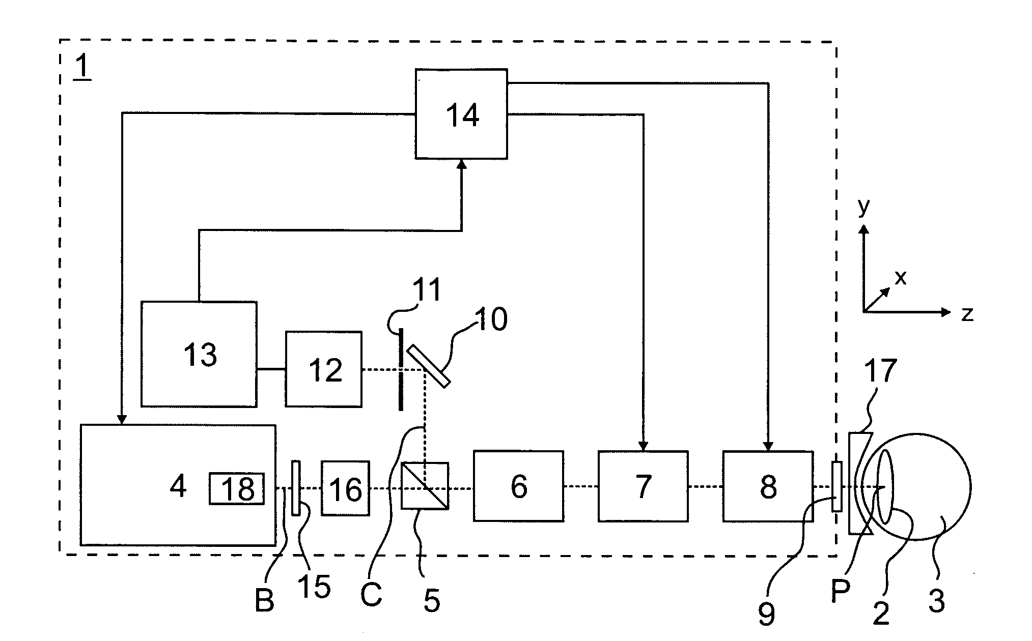
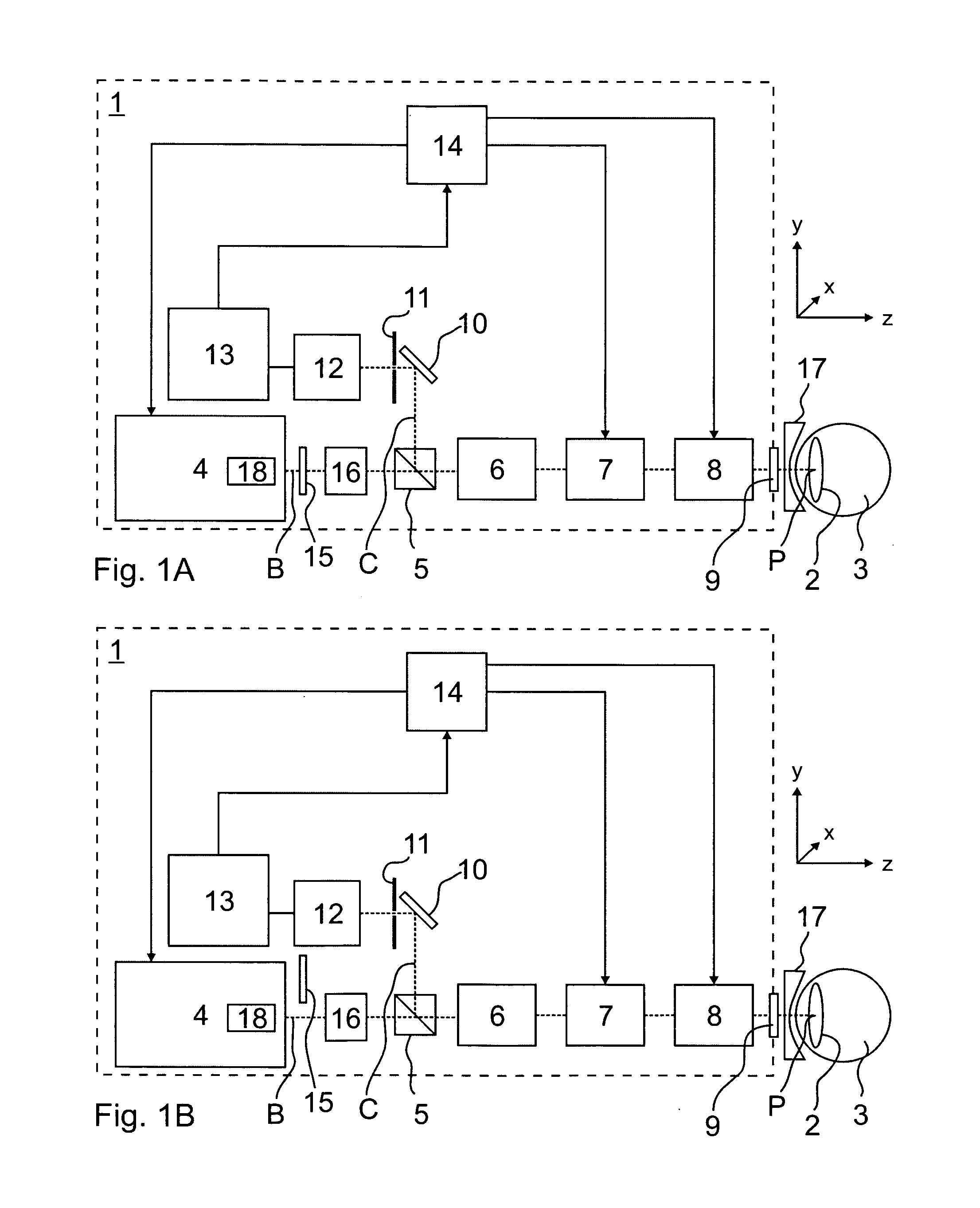
[0056]FIG. 1 shows an exemplary ophthalmological laser system 1 for combined analysis and therapy of a presbyopia of a crystalline lens 2 of an eye 3. According to the invention, this system also allows for treatment of the cornea (not depicted) of the eye 3. In the illumination beam path B, the laser system 1 exhibits a laser 4, a polarization beam splitter 5, scan optics 6, a scanner unit 7, focusing optics 8, and an optical phase retardation system 9; a deflection mirror 10, a confocal aperture diaphragm 11, and a detector 12, which form a decoupled detection beam path C; and an amplifier 13 and a control unit 14. In addition, a modulator 16, e.g., an acousto-optical modulator (AOM, AOTF), is provided in the illumination beam path. A contact glass 17 with an immobilization device for the eye 3 is arranged between the laser system 1 and the eye 3 and behind which is the examination region. Other embodiments for the realization of the solution, according to the invention, are possi...


PUM


Abstract

An ophthalmological laser system for photodisruptive irradiation of ocular tissue, including a crystalline lens or a cornea. The system includes an ultra-short pulse laser, the radiation of which is focusable as illumination light via an illumination beam path including a scanner unit and focusing optics. A control unit is programmed to execute determining irradiation control data for photodisruptions at irradiation points in an interior of the ocular tissue distributed three-dimensionally and non-equidistantly to create at least one predetermined target incision. The laser system then irradiates the ocular tissue according to the determined irradiation control data.

Description

PRIORITY CLAIM[0001]The present application is a National Phase entry of PCT Application No. PCT / EP2010 / 001499, filed Mar. 11, 2010, which claims priority from German Application No 102009012873.5, filed Mar. 12, 2009, the disclosures of which are hereby incorporated by reference herein in their entirety.FIELD OF THE INVENTION[0002]The invention relates to an ophthalmological laser system for the photodisruptive irradiation of ocular tissue, particularly a crystalline lens or a cornea, with a laser, the radiation of which is focusable as illumination light via an illumination beam path, which includes a scanner unit and focusing optics, in an examination region. Furthermore, the invention relates to a method for the photodisruptive irradiation of ocular tissue, particularly a crystalline lens or a cornea, particularly an operating method for an ophthalmological laser system.BACKGROUND[0003]Accommodation is the ability of the eye to create a sharp image on the retina of an object loc...

Claims


Application Information

Patent Timeline
Patent Type & Authority Applications(United States)
IPC IPC(8): A61F9/01
CPCA61F9/008A61F9/00838A61F2009/00897A61F2009/00872A61F2009/00895A61F2009/0087
Inventor DICK, MANFREDREICH, MATTHIASGREBNER, DIETER
Owner CARL ZEISS MEDITEC AG
Why Eureka
Try Eureka