MEMS-type pressure pulse generator

a technology of pressure pulse generator and nems type, which is applied in the direction of loudspeakers, instruments, sound producing devices, etc., can solve the problems of sound level, bass restoration, and limited amplitude of nems type, and achieve the effect of easy monitoring of the shape of the pressure pulse caused by the pressure pulse, good response linearity, and good controllability

Inactive Publication Date: 2012-01-26
COMMISSARIAT A LENERGIE ATOMIQUE ET AUX ENERGIES ALTERNATIVES
View PDF0 Cites 31 Cited by
  • Summary
  • Abstract
  • Description
  • Claims
  • Application Information

AI Technical Summary

Benefits of technology

[0038]When the actuation is done electrostatically, by surface variation, or in the case of actuation by thermal effect, the invention resolves the problem of the deformation amplitude of the nonlinear membrane as a function of the applied voltage. This also contributes to an effective monitoring of the rising and falling edge of each pressure or depression or partial vacuum pulse.
[0039]Having a capacitive means as actuating means makes it possible to have a good response linearity (for example measured by the ratio between the voltage applied to the actuating means and the displacement amplitude of the membrane) and therefore to be able to easily monitor the shape of a pressure pulse caused in the cavity.

Problems solved by technology

However, the actuating amplitude of these MEMS membranes is very limited.
Furthermore, given the dimensions of these MEMS components, the restoration of bass (which requires a greater displacement amplitude to offset the decrease in sound levels caused by the drop in frequency, the sound level being directly proportional to the frequency) is practically impossible with acceptable levels.
This results in a significant distortion even for low sound levels.
This configuration makes it practically impossible to generate identical pressure or depression or partial vacuum pulses.
Another problem is that the use of an electrostatic actuation with air gap variation involves a nonlinear deformation amplitude of the membrane as a function of the applied voltage.
This makes it very difficult to control the rising and falling edge.
The deformation as a function of time therefore cannot be electrically controlled.
This also makes it impossible to attenuate the vibration bounces that have a substantial impact on the sound characteristics of the device.
There is then a risk of adhesion of the two armatures of the capacitance of the electrostatic actuator.
This consequently greatly limits the accessible deformation amplitude for a given maximum voltage (amplitude / gap and gap / max voltage compromise).
This limitation is due in particular to the low accessible vibration amplitudes for each of the cMUT membranes.
Reliability problems with this type of device are due to the charging of the dielectrics, already mentioned in the article cited above.
Difficulties can also be mentioned in generating pressures of different frequencies on the same component in the case of a coupled use of these cMUTs in imaging (>10 MHz) and therapy (<5 MHz).
This aspect makes the current technology very complicated.

Method used


Image

  • MEMS-type pressure pulse generator
  • MEMS-type pressure pulse generator
  • MEMS-type pressure pulse generator

Examples


third embodiment

[0128]A third embodiment is shown in side and top views in FIGS. 4A and 4B. FIG. 4A is a cross-sectional view along a plane, the outline A1A′1 of which is visible in FIG. 4B (top view).

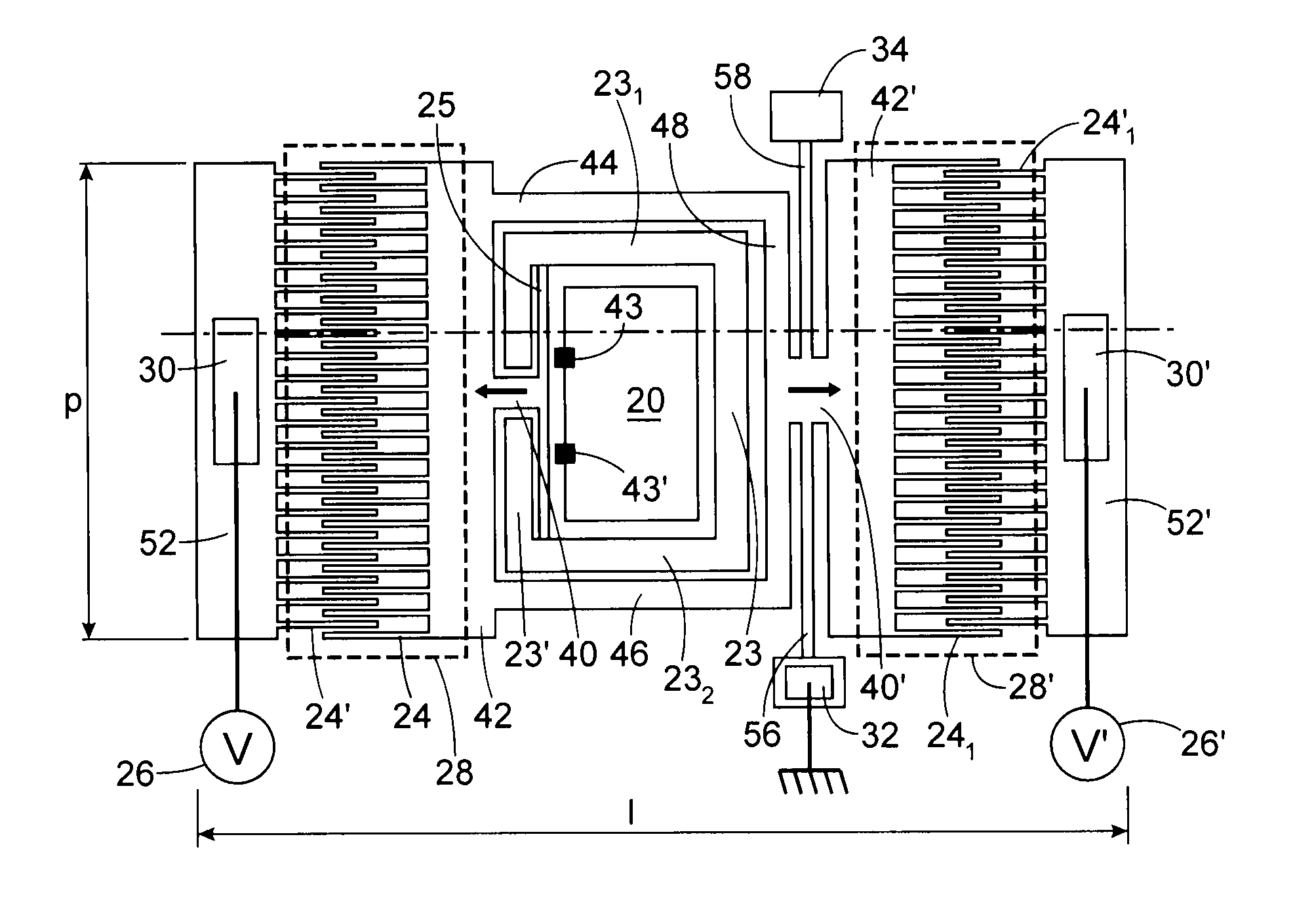
[0129]A difference relative to FIGS. 2A-2B lies in the contacts 301, 30′1, 321, which here are on the rear face, i.e. on or in the substrate 101. Another difference lies in the structure of the wall 25.

[0130]The structure of the wall 25 is of the type having a rigid central part framed by two parts 253, 255 forming a “spring,” and which are deformable. Under the effect of the actuating means, the rigid part moves, the parts 253, 255 being deformed. These parts also return the rigid part to the initial position when the actuating means returns to its initial state, after excitation. These parts 253, 255 form spring connections at the ends of the rigid part. Here there is a so-called “piston” effect or movement of the mobile part. But it would also be possible to use, in this embodiment, the deformable ...

fifth embodiment

[0157]A fifth embodiment, illustrated in FIG. 6 in top view, includes means for producing a thermal excitation (through bimorph or asymmetrical effect) applied to a deformable membrane. This means is for example of the thermal actuator or piezoelectric type. The structure of this means and its operation is for example described in the article “Time and frequency response of two-arm micromachined thermal actuators R Hickey et al- 2003 J. Micromech. Microeng. 13-40.” Information regarding the operation of the bimorphic actuator is available at: http: / / www.pi-france.fr / PI%20Universite / Page20%20.htm. In summary, a constraint in the plane of one of the layers of a multi-layer stack (if there are two, it is called a bimorph) causes a displacement of this stack in the direction perpendicular to the plane of the layers.

[0158]Two sets of means for producing a thermal excitation are shown in FIG. 6, but there can be only one, in which case there is actuation in only one direction (either pres...

sixth embodiment

[0159]A sixth embodiment is shown in FIGS. 7A (cross-sectional side view) and 7B (top view).

[0160]It includes a means for producing an electrostatic actuation, of the flat piston type, on several parallel cavities 20, 20′, 20″, 20″′ (in particular for cMUT). These cavities, or their corresponding openings 21, can be closed by a flexible membrane 281, which for example makes it possible to prevent dust or moisture from entering the device in the case of a loudspeaker-type operation. In the case of cMUT operation, this membrane can also vacuum seal or partially vacuum seal the device (a cMUT working at the resonance). It can be noted that this membrane 281 can also be arranged on the other face of the substrate 102 as illustrated by the membrane 281′ in broken lines in FIG. 7A. This closing system of the cavity 21 can also be implemented in the context of the preceding embodiments.

[0161]This device also includes two cavities 280, 280′, each forming a “back volume,” which is closed and...


PUM


Abstract

The invention relates to a device for generating or recovering acoustic energy, including:
    • at least one first deformable cavity (20) for receiving an ambient atmosphere, made in a first substrate, delimited by at least one wall including at least one mobile or deformable wall (25), and a means for making the cavity communicate with an ambient atmosphere,
    • a means (24, 24′, 241, 24′1) for actuating a displacement or deformation, in the plane of the sensor, or to recover energy resulting from a displacement or deformation, in the plane of the sensor, of said mobile or deformable wall.

Description

TECHNICAL FIELD AND PRIOR ART[0001]The invention relates to a MEMS- and / or NEMS-type pressure pulse generator.[0002]It makes it possible to produce MEMS loudspeakers, digital MEMS loudspeakers, and cMUTs (“capacitive Micromachined Ultrasonic Transducer”). In fact, the generation of pressure pulses primarily concerns two applications: loudspeakers and cMUTs.[0003]There are two approaches to making MEMS loudspeakers: a traditional approach, of the analog loudspeaker type, and another approach, of the digital loudspeaker type.[0004]Analog loudspeakers are formed by a membrane actuated by electromagnetic, electrostatic, or piezoelectric means, at the frequency of the sound one wishes to restore. The restored sound volume will be proportional to the displacement amplitude of the membrane.[0005]Some are made in MEMS form, as for example described in the article by Neumann J J et al, 2001, CMOS-MEMS membrane for audio frequency actuation IEEE Int. Proc. MEMS 2001- pp 236-9.[0006]FIG. 1A sh...

Claims


Application Information

Patent Timeline
Patent Type & Authority Applications(United States)
IPC IPC(8): G10K15/04
CPCB06B1/0292H04R1/005H04R17/00H04R2201/003H04R23/002H04R2400/00H04R31/00H04R19/005
Inventor ROBERT, PHILIPPE
Owner COMMISSARIAT A LENERGIE ATOMIQUE ET AUX ENERGIES ALTERNATIVES
Why Eureka
Try Eureka