Method and apparatus for monitoring a property of a sample

a technology of a sample and a property, applied in the direction of scanning probe techniques, instruments, reradiation, etc., can solve the problems that the methods known to date do not allow satisfactory monitoring of processes and dynamics at the nanoscal

Active Publication Date: 2012-01-26
UNIVERSITY OF MELBOURNE
View PDF7 Cites 101 Cited by
  • Summary
  • Abstract
  • Description
  • Claims
  • Application Information

AI Technical Summary

Benefits of technology

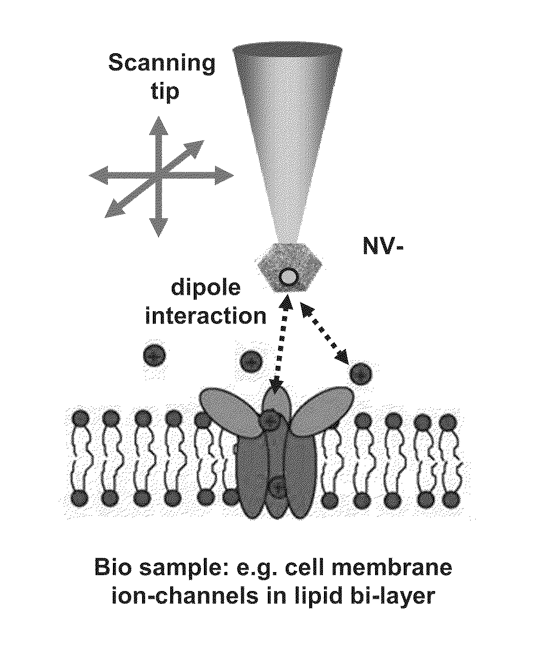
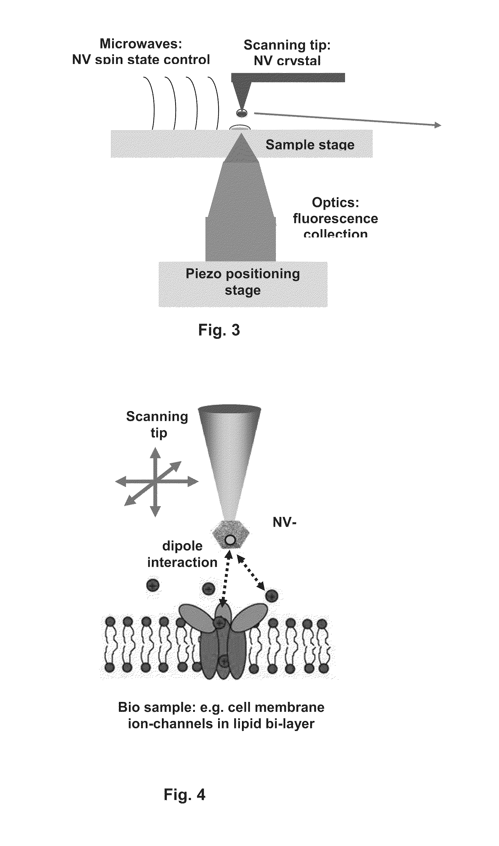
[0021]In one specific embodiment of the present invention the method allows monitoring a function of biological samples typically at the nanoscale. The method may comprise detecting fluctuations or particle, such as ions, in the surface or bulk of the sample. The sample may for example be a cell membrane and may comprise a bi-lipid. The sample may comprise ion channels, such as channels though which single ions diffuse. The method may comprise exposing the sample, or the sample and the quantum probe, to a liquid, such as water, a salt-containing solution, or any other suitable solution. The method may further comprise detecting a change (usually an increase) in quantum decoherence rate caused by an influence of a spin of the particle on the quantum pr...

Problems solved by technology

However, the methods known to date do not allow monitoring ...

Method used


Image

  • Method and apparatus for monitoring a property of a sample
  • Method and apparatus for monitoring a property of a sample
  • Method and apparatus for monitoring a property of a sample

Examples


example ii

Imaging the Position and Spin State of Ferritin Molecules

[0146]The following will consider the imaging of (bio)molecules with large uncompensated spin, such as 15 Horse-spleen Ferritin34,35 or Fe836. Here, the point is neither to image an individual spin37 or image the location of the molecules22,38,39 as both can be done with existing technology. We show that qubit probe imaging can both map the location of the spins and probe their magnetic dynamics.

[0147]The decoherence introduced at the probe qubit will be a function of both the interaction strength and the flipping rate of the sample spins. As we are considering large sample spins in a static magnetic field at low temperature, we will assume that the flipping rate is slow on the scale of the probe Hamiltonian. This means that the spectral response of the qubit is split, with the separation between the peaks giving the effective difference in the Hamiltonian between the two sample spin states.

[0148]We compute the coupling streng...

example i

Method: Decoherence Due to a Bath of 1 / F Fluctuators

[0163]We wish to use a simple model of the decoherence felt by a probe (charge−)qubit interacting with a bath of 1 / f fluctuators23,24,33. The numerical parameters used for such a model vary greatly depending on the system and even from sample to sample. Here we are interesting in the functional dependence, rather than the explicit values. We draw heavily from references [33] and [24] as an example.

[0164]Consider a qubit interacting with a bath of fluctuators via an interaction Hamiltonian Hint which has the form

Hint=σz∑jvjbj†bj(14)

where σz acts on the qubit and bj destroys (creates) an electron in a localized state in the bath.

[0165]The spectral response from the jth fluctuator (in the fast fluctuator limit) is given by

sj(ω)∝vj2γjγj2+ω2(15)

where νj is the strength of the fluctuator which fluctuates with rate γj The total spectral response is then the sum over each of the fluctuators

S(ω)=Σjsj(ω)  (16)

and a simplified Golden rule mod...


PUM


Abstract

The present disclosure provides a method of monitoring a property of a sample, such as a nanoscopic property of the sample. The method comprises the steps of providing a quantum probe having a quantum state and exposing the quantum probe to the sample in a manner such that the property of the sample, in the proximity of the quantum probe, affects quantum coherence of the quantum probe. The method also comprises detecting a rate of quantum decoherence of the quantum probe to monitor the property of the sample. Further the present disclosure provides an apparatus for monitoring a property of a sample.

Description

TECHNICAL FIELD[0001]The present invention relates to a method and apparatus for monitoring a property of a sample. The present invention relates particularly, though not exclusively, to a method and apparatus for monitoring a nanoscopic property of a sample.BACKGROUND ART[0002]Advancement of our understanding of biological and condensed matter systems would greatly benefit from an ability to monitor the structure and dynamics at a molecular level. For example, cell membranes include ion channels and detailed information concerning the activity of the ion channels would be very useful for advancing our understanding of the function of cell membranes and cells.[0003]Two stage quantum probes have been used as a sensitive spatial electrometer or magnetometer to produce images. However, the methods known to date do not allow monitoring processes and dynamics at the nanoscale in a satisfactory manner. There is a need for technological advancement.SUMMARY OF THE INVENTION[0004]The present...

Claims


Application Information

Patent Timeline
IPC IPC(8): G01R33/20
CPCB82Y15/00B82Y35/00G01R33/326G01Q60/00G01Q70/14G01N24/10G01Q60/42
Inventor HOLLENBERG, LLOYDCOLE, JARED
Owner UNIVERSITY OF MELBOURNE
Why Eureka
Try Eureka