Protective-control measuring system and device and data transmission method

Inactive Publication Date: 2012-01-26
NAT UNIV CORP YOKOHAMA NAT UNIV +1
View PDF3 Cites 4 Cited by
  • Summary
  • Abstract
  • Description
  • Claims
  • Application Information

AI Technical Summary

Benefits of technology

[0014]According to the present invention, there are provided highly secure and reliable protective-control measuring system and device, and data transmission method using a practical in

Problems solved by technology

The problem always brought in this case is a cyber security countermeasure.
Hence, when the performance of computing machinery greatly improves or computationally efficient methods for solving the problem thereof is found in a future, such security algorithms based on computational complexity become insecure from the standpoint of security issues, so that it is necessary to replace such security algorithms with another secure algorithm.
Moreover, the protective-control measuring system often needs to be operated for a long period nondisruptively, which resu

Method used


Image

  • Protective-control measuring system and device and data transmission method
  • Protective-control measuring system and device and data transmission method
  • Protective-control measuring system and device and data transmission method

Examples


first embodiment

[System Configuration]

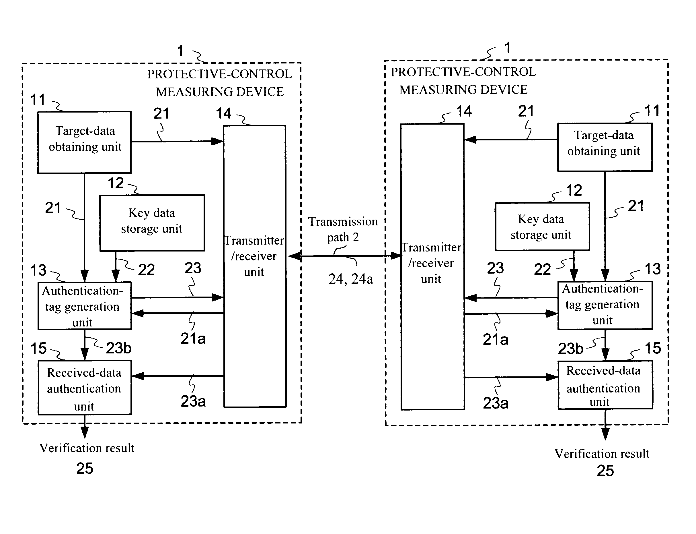
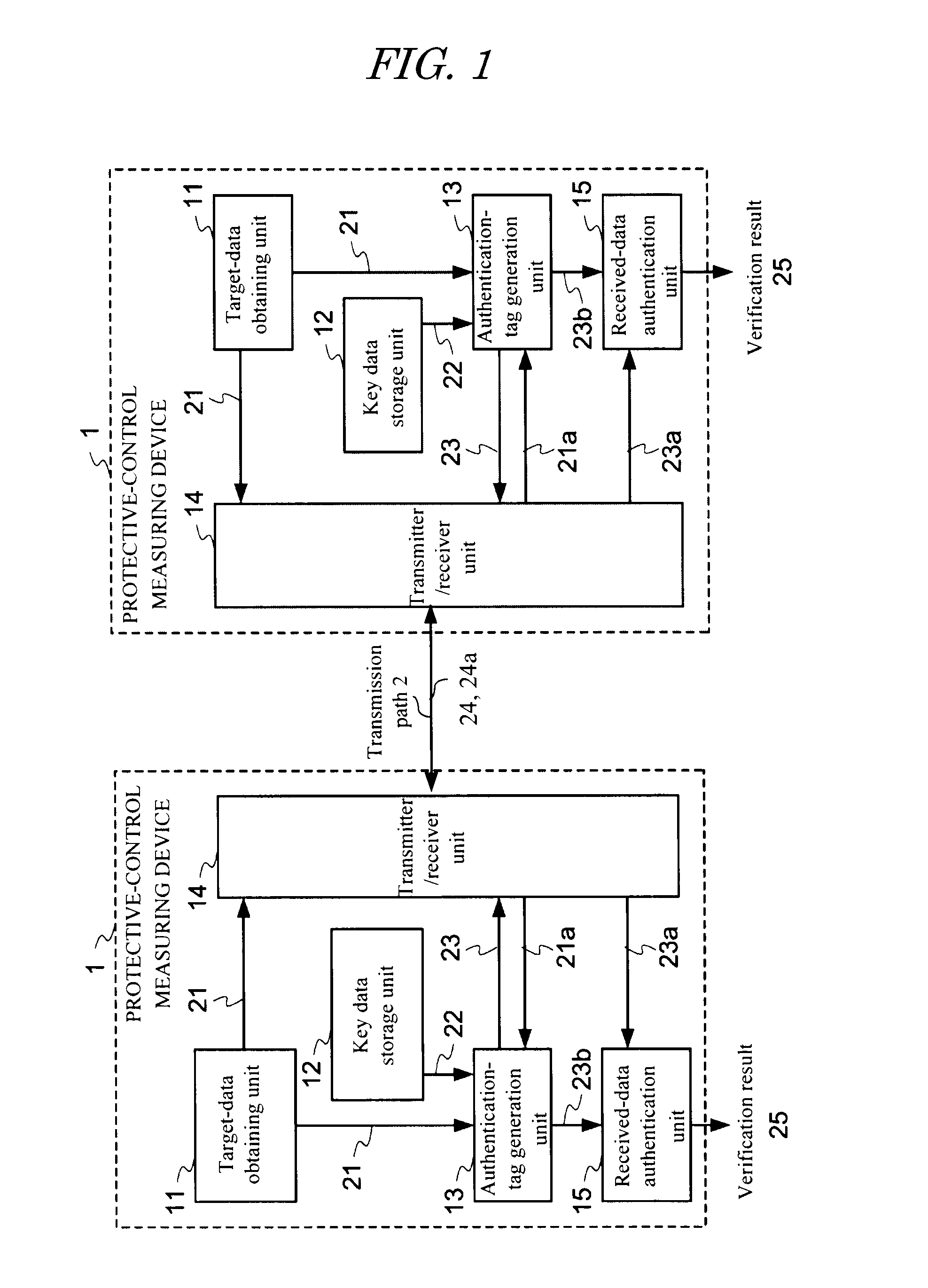
[0031]FIG. 1 is a block diagram showing a configuration of a protective-control measuring system of the first embodiment according to the present invention. The protective-control measuring system shown in FIG. 1 includes two protective-control measuring devices 1 having the same configuration and connected together through a transmission path 2. The transmission path 2 is configured by various medium, such as an optical fiber, a microwave link, or a power line. Specific examples of transmission target data exchanged between the protective-control measuring devices 1 are electric-line current data measured between both terminals of an electric line, a breaker shut-off instruction, and various protective-control data like a device state in the substation. In the present specification, such transmission target protective-control data is referred to as “transmission target data” or “(transmission target) main data”.

[0032]The protective-control measuring device 1 i...

seventh embodiments

Second to Seventh Embodiments

[0061]Protective-control measuring systems according to the second to the seventh embodiments to be discussed later are all the protective-control measuring systems (see FIG. 1) having the same system configuration as that of the first embodiment. The second to the fifth embodiments are modified examples in which a process and data structure are partially changed or further unit is added, and the sixth and the seventh embodiments are application examples to a current-differential protection system and a substation control system. Accordingly, in the explanation for the second to the seventh embodiments below, only the features different from the first embodiment will be explained and the explanation for the same structural element as that of the first embodiment will be basically omitted.

second embodiment

[0062]In the above-explained first embodiment, the key data table and the authentication matrix shown in FIG. 4 are used as the key data. In the second embodiment, the key data is further divided into a fixed key matrix U commonly used and a disposable key vector v changed for each sending, so that the size of the authentication tag and that of the key data are reduced, and thus the authentication-tag generating calculation amount is reduced.

[0063]As a result of dividing the key data into the fixed key matrix U and the disposable key vector v, the authentication-tag generating algorithm by the authentication-tag generator unit 13 (see FIG. 1) obtains an authentication tag vector y through a following vector calculation.

y=xU+v [0064]where x is main data vector;[0065]U is a fixed key matrix; and[0066]v is a disposable key vector.

[0067]FIG. 6 is a diagram showing characteristic authentication-tag generating algorithm and authentication algorithm in the transmitter device 1T and the rec...


PUM


Abstract

According to one embodiment, when sending a transmission target main data 21, an authentication-tag generator unit 13 generates an authentication tag 23 by using a main data 21 and a key data 22 stored in a key-data storage unit 12. A transmitter/receiver unit 14 adds the authentication tag 23 to the main data 32 sends as a transmission data. When receiving the received data 24a, the transmitter/receiver unit 14 divides the received data into a main data 21a and an authentication tag 23a. The authentication-tag generator unit 13 generates an authentication tag 23b for comparison. A received-data authentication unit 15 determines whether or not those the received authentication tag 23a and the authentication tag for comparison 23b match with each other. A different key data is used every time upon the authentication-tag generation and use time of each key data during a set period is restricted.

Description

TECHNICAL FIELD [0001]The present invention relates to a system including a plurality of devices connected together through a communication network, and more particularly, to a protective-control measuring system for a power system.RELATED ART [0002]Recently, application of general-purpose network technologies, such as Ethernet (registered trademark) and TCP / IP, to a protective-control measuring system becomes popular. The problem always brought in this case is a cyber security countermeasure. Regarding the security technology for power communication, Non-patent Literature 1 discloses an authentication scheme using the SHA-1 algorithm.[0003]However, various security algorithms currently popular like SHA-1 (Secure Hash Algorithm 1) defined in Non-patent Literature 1 are for assuring the security based on computational complexity as disclosed in Non-patent Literature 2. Hence, when the performance of computing machinery greatly improves or computationally efficient methods for solving...

Claims


Application Information

Patent Timeline
IPC IPC(8): H04L9/32
CPCH04L9/0897H04L2209/12H04L9/3228H04L9/16H04L9/088H04L9/3242Y04S40/20H04L9/0861H04L9/3247H04L2209/24
Inventor KATAYAMA, SHIGEKISEKIGUCHI, KATSUHIKOFUKUSHIMA, KAZUTOMATSUMOTO, TSUTOMU
Owner NAT UNIV CORP YOKOHAMA NAT UNIV
Why Eureka
Try Eureka