Pipe insulation system

a technology of pipe insulation and pipe body, which is applied in the direction of service pipe systems, pipe heating/cooling, mechanical equipment, etc., can solve the problems of not always meeting the theoretical design requirements, code does not provide any specific direction, and extensive building damage, etc., to achieve the effect of facilitating heat transfer

Inactive Publication Date: 2012-02-02
INSULATION SYST
View PDF6 Cites 1 Cited by
  • Summary
  • Abstract
  • Description
  • Claims
  • Application Information

AI Technical Summary

Benefits of technology

[0010]In this regard, the present invention provides a method and system that, as opposed to the tenting method described above, incorporates a modular shell system of a hard insulation material, such as polystyrene. The intention of this design is to provide individual pieces of polystyrene fabricated in a geometric shape that encapsulates the pipe in insulation. In an attic installation for example, the entire insulation component is inserted over the pipe and into the space between the building structural wood framing members resting on the interior sheathing below. By placing a series of these interlocking insulating modules along a pipe that is run perpendicular to the building construction members, the piping is encapsulated in a continuous insulating system along its entire length. An intended feature of this design is to facilitate natural heat flow into the pipe in a manner similar to my original design with an open pipe slot cavity in the insulating module that allows natural convection heat to pass up through the elongated piping slot, allowing it to come into contact with this piping.
[0011]This design provides a modular system that is more resilient and is less prone to displacement by inadvertent contact. Through the use of this system a more effective insulating system can be installed in comparison to present standard practice of trade even if pipes cannot be installed in the more desirable position directly against a building's interior sheathing.
[0013]Accordingly, it is an object of the present invention to provide a method and system for insulating piping that is specifically configured and designed for applications in ceiling construction where the pipes are prone to freezing. It is a further object of the present invention to provide a method and system of insulating piping, such as sprinkler piping in ceiling construction that reliably insures that the piping is protected from freezing by insuring that the piping is maintained as near to the ambient temperature of the interior of the structure as possible. It is still a further object of the present invention to provide a system for insulating piping that reliably positions an uninterrupted thickness of insulation material behind the piping such that the insulation material is positioned between the piping and the exposed attic environment while including a heat transfer cavity to facilitate heat transfer from the interior of the building and into the piping.

Problems solved by technology

The difficulty created in these instances is that during the winter the temperature outside the wall construction and often within the wall cavity itself fall below 32° F., the freezing point of the water contained within these piping systems.
While theoretically the piping can be protected from freezing provided that it is positioned on the interior half of the wall where temperature can he seen to be above 38° F., actual practice does not always meet the theoretical design requirements as will be discussed below.
One issue with such code provisions, however, is the fact that the code does not provide any specific direction as to how such protection against freezing should be provided.
Further, while these code provisions apply to domestic water supplies, the difficulty arises in that the parallel code relating to heating systems has not provided any requirements regarding the protection of hydronic piping from freezing.
This situation is further aggravated because the lack of direction a code level has translated directly into a lack of industry support for the installation of insulation on hydronic piping in exterior walls.
As a result, there have been a large number of pipe failures directly tied to the freezing of the piping installed in exterior walls, wherein the pipe failure has caused extensive building damage.
It has been reported that building damage due to frozen pipes is second in the United States only to hurricane damage.
While in theory such a practice should work, in most cases the actual installation does not comport with the theoretical ideal.
Part of the problem with this methodology is that the batting insulation that is used is not intended for this particular application.
When draped over the pipe it becomes compressed, reducing its insulation value.
Also, by creating a large building void space, this defeats the Energy Conservation Code, as well as Energy Star Guidelines, for building construction, and additionally creates large air spaces within building cavities that can lead to condensation, as well as mold growth.
Also, freezing often occurs in pipes insulated in this manner due to inadvertent contact by building occupants, wind, or even animal contact which dislodges this insulation allowing cold draft contact.
When this piping arrangement cannot be modified and the possibility of passing this piping through these members by drilling a hole is not desirable for the installer, still, a methodology needs to be applied to protect this piping from freezing.
The problem that most people do not appreciated about the prior art insulation is that they are designed to prevent heat loss from the interior of the pipe to the exterior of the pipe.
These insulation materials are not designed to address piping installed in locations for a long time that do not contain heated or moving water and this insulation is only intended to satisfy the requirements of the International Energy Conservation Code in reducing energy losses.

Method used


Image

  • Pipe insulation system
  • Pipe insulation system
  • Pipe insulation system

Examples


Embodiment Construction

[0027]Now referring to the drawings, method and system for insulating piping installed in an exterior wall is generally shown and illustrated. As was stated above, the present invention generally provides an improved method and system for effectively insulating piping located in an exterior wall or ceiling construction in a manner that protects the piping from freezing.

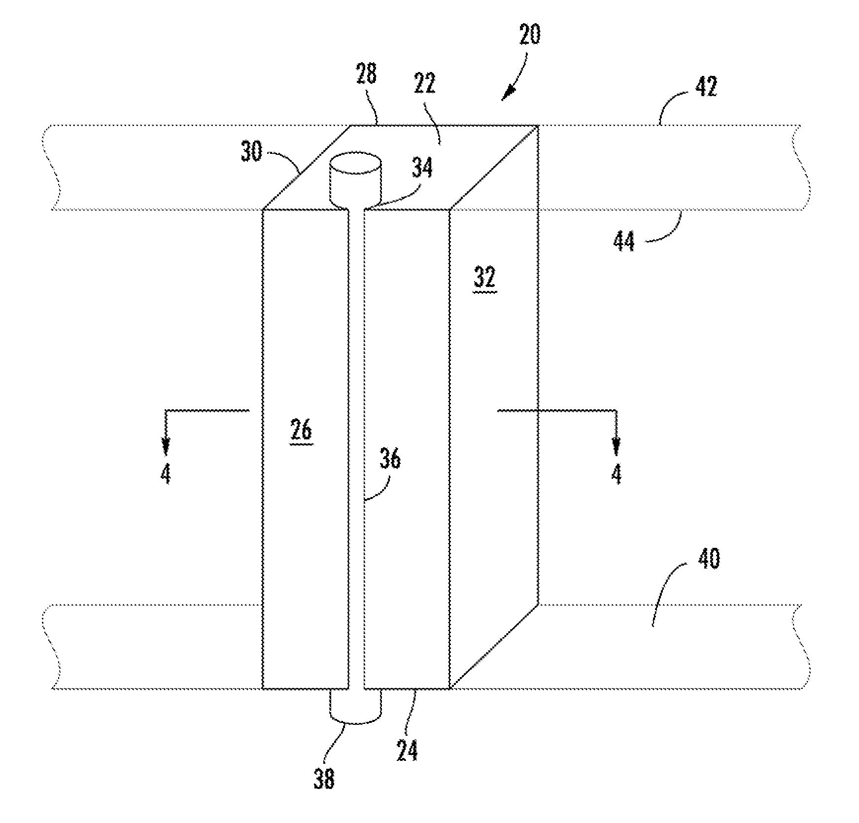
[0028]Turning to FIG. 3, it can be seem that in its most general form, the system of the present invention provides for an insulation block 20 that is dimensioned particularly for installation into a building wall cavity. The insulation block 20 is generally regular in cross-section and is longitudinal extending from a proximal end 22 to a distal end 24. The insulation block 20 includes a front surface 26, a rear surface 28 and two side surfaces 30, 32 that all extend along a length of the insulation block 20 between the proximal 22 and distal 24 ends. The insulation block 20 can be seen to include at least one cavity...


PUM


Abstract

A modular shell system of a hard insulation material fabricated in a geometric shape that encapsulates a pipe in insulation is provided. In an attic installation for example, the entire insulation component is inserted over a pipe and into the space between the building structural wood framing members resting on the interior sheathing below. By placing a series of these interlocking insulating modules along a pipe that is run perpendicular to the building construction members, the piping is encapsulated in a continuous insulating system along its entire length. This design facilitates natural heat flow into the pipe with an open pipe slot cavity in the insulating module that allows natural convection heat to pass up through the elongated piping slot, allowing it to come into contact with this piping.

Description

CROSS-REFERENCE TO RELATED APPLICATIONS[0001]This application is a continuation-in-part and claims priority from earlier filed U.S. Utility patent application Ser. No. 12 / 246,588, filed Oct. 7, 2008 and U.S. Provisional Patent Application No. 61 / 452,926, filed Mar. 15, 2011.BACKGROUND OF THE INVENTION[0002]The present invention relates generally to a method and system for insulating piping. More specifically, the present invention relates to a method and system for effectively insulating piping located in an exterior wall construction in a manner that protects the piping from freezing.[0003]In the construction of residential and commercial structures a variety of piping systems are installed to allow delivery of water to various plumbing fixtures such as sinks and toilets. Further, hydronic piping is installed to circulate a fluid medium, which is some cases is simply water, to effect heat transfer in order to heat the space. Often, due to the design of the space or the location of ...

Claims


Application Information

Patent Timeline
Patent Type & Authority Applications(United States)
IPC IPC(8): E04B1/74E04C2/52
CPCF16L59/121F16L5/00
Inventor CERTUSE, JR., JOHN
Owner INSULATION SYST
Why Eureka
Try Eureka