
Impulse type shock wave flash dyeing machine

Inactive Publication Date: 2012-02-02
ZHAO CHENG JIANG
View PDF12 Cites 5 Cited by
  • Summary
  • Abstract
  • Description
  • Claims
  • Application Information

AI Technical Summary

Benefits of technology

[0023]In use, the fast moving air, steam, dyes, processing agents and low-temperature plasma blast the fibrous fabric. As the fibrous fabric turns or descends, energy transfer may be carried out efficiently from the fast moving air, steam, dyes, processing agents and low-temperature plasma to the fibrous fabric. In addition, the dyes and processing agents are imparted with a high amount of kinetic energy and are in the form of fine mist or individual molecules as they flow in the air flow. The fine mist of dyes and processing agents violently collide with the direction-changing fibrous fabric in the manner of elastic collision (the collision between air or gas and the fibrous fabric) or inelastic collision (the collision between processing agents, dyes or plasma and the fibrous fabric). The inelastic collision results in highly efficient transfer of kinetic energy and hence the fibrous fabric would move faster. The inelastic collision also supplies sufficient amount of fluid to generate the effect of cavitation. In addition, a reflective motion plate can generate a high-speed wavy motion on the fibrous fabric. The air pressure of the upper portion of the fibrous fabric is greater than the air pressure of the lower portion of the fibrous fabric. The difference in air pressure prompts the fibrous fabric to move in a violent high-frequency wavy motion and to spread out as the fibrous fabric passes the reflective motion plate.
[0039]A tenth object of the present invention is to provide an impulse type shock wave flash dyeing machine in which the circulation wheel of the prior art is not needed at the front entry of the fabric guiding tube and the fabric flop wheel of the prior art is not needed at the outlet of the fabric guiding tube. Therefore, safety may be enhanced and a user would not be affected by the presence of the circulation wheel. In addition, the fabric would not be damaged by the fabric circulation wheel and the jamming. Also, the speed at which the fabric moves would not be limited by the fabric flop wheel as the fabric passes the fabric guiding tube.

Problems solved by technology

However, most dyeing machines of the prior art have only a single application and there has not been any dyeing machine that has multiple functions and multiple applications and that is environmental friendly on the market.
Because water has been used as the medium in the wet type process of textile products, the textile dyeing and finishing industry has been discharging a lot of contaminated water.
Such trend is a tough challenge to the textile dyeing and finishing industry.
In fact, global warming and climate change have become urgent issues.
Therefore, they consume an excessive amount of water and energy and seriously pollute the environment.
Also, their processing costs are too high and they seriously damage the eco system.
Many problems and disadvantages still can not be solved in the dyeing machines of the prior art (including the spread-out type and non-spread-out type air flow dyeing machines and the traditional injection type dyeing machine).
Such problems and disadvantages include the right portion of the fabric having a different color from that of the left portion, the inconsistency in color for the same patch of fabric, uneven application of the dyes, the fabric circulation wheel being unable to move in sync with the nozzles, the fabric not able to move fast enough, damages caused by friction and collision, the fibers of the fabric being broken by the excessive amount of force exerted by the nozzles, the clogging of the nozzles and the filtering units, the fabric unable to have a pleasant feel, the low efficiency in the bio enzyme process, processes being carried out too slowly, the machine not having enough functions and hence the processes being limited, excessive use of energy and water, etc.
Therefore, the cost for the treatment of contaminated water skyrockets.
Also, the fabric circulation wheel poses a danger to the users.
In addition, finished fabric may not have a good feel.
Poor design is the main reason for all of the aforesaid problems.
For example, the inconsistency in color is caused by the more-than-one processing tanks and the uneven division or distribution of the dyes and air flow.
It is difficult to equally divide the fluid or flow in a tube into two exactly equal parts (in the prior art, a single tube is divided into two tubes, two tubes are then divided into four tubes and four tubes are divided into eight tubes), resulting the inconsistency in color.
In addition, a modification or re-dyeing may be needed when there is an unsatisfactory result and such modification or re-dyeing would be a waste of energy and water and increase the production cost.
If the dye dissolves in an excessive amount of the operating solution in the dyeing process, the operating solution may reduce the contact and interaction between the dye or processing fluid and the fabric.
However, it is difficult to process and purify the residual solution after the dyeing process.
Regarding dispersal dye, which has a level of solubility, because it does not have ion radicals, the dyeing process is quite difficult to carry out.
A large amount of dispersion agent has to be used to make it suspending in the operating fluid and the state of such suspension is difficult to maintain.
In addition, the residual solution is difficult to purify.
Regarding synthetic fiber, because it is difficult for such fiber to dissolve in water, it is difficult for the dye to diffuse inside the synthetic fiber.
With regard to natural fiber, it has a complicated structure and many cavities, which are filled with air.
Therefore, it is difficult for the dye to enter the fibers and dyeing process takes a longer time.
In the past, dyeing at the boiling point is used for the dyeing of wool and such dyeing takes a longer time.
Therefore, such dyeing consumes more energy and wool fiber can be damaged.
In addition, because reactive dye may react with water at high temperatures and in alkaline solution, the efficiency of dyeing is reduced.
Also, after the dyeing process, both the residual solution of the dyeing and the unfixed dyes in the post-treatment are highly polluted solutions.

Method used


Image

  • Impulse type shock wave flash dyeing machine
  • Impulse type shock wave flash dyeing machine
  • Impulse type shock wave flash dyeing machine

Examples


Embodiment Construction

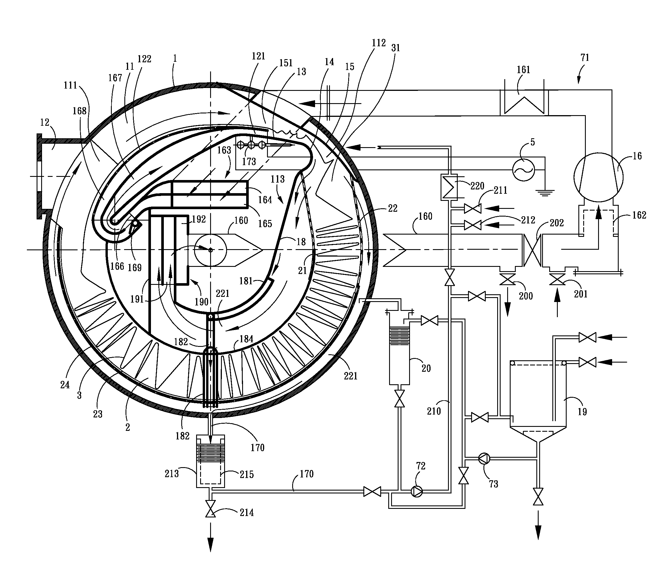
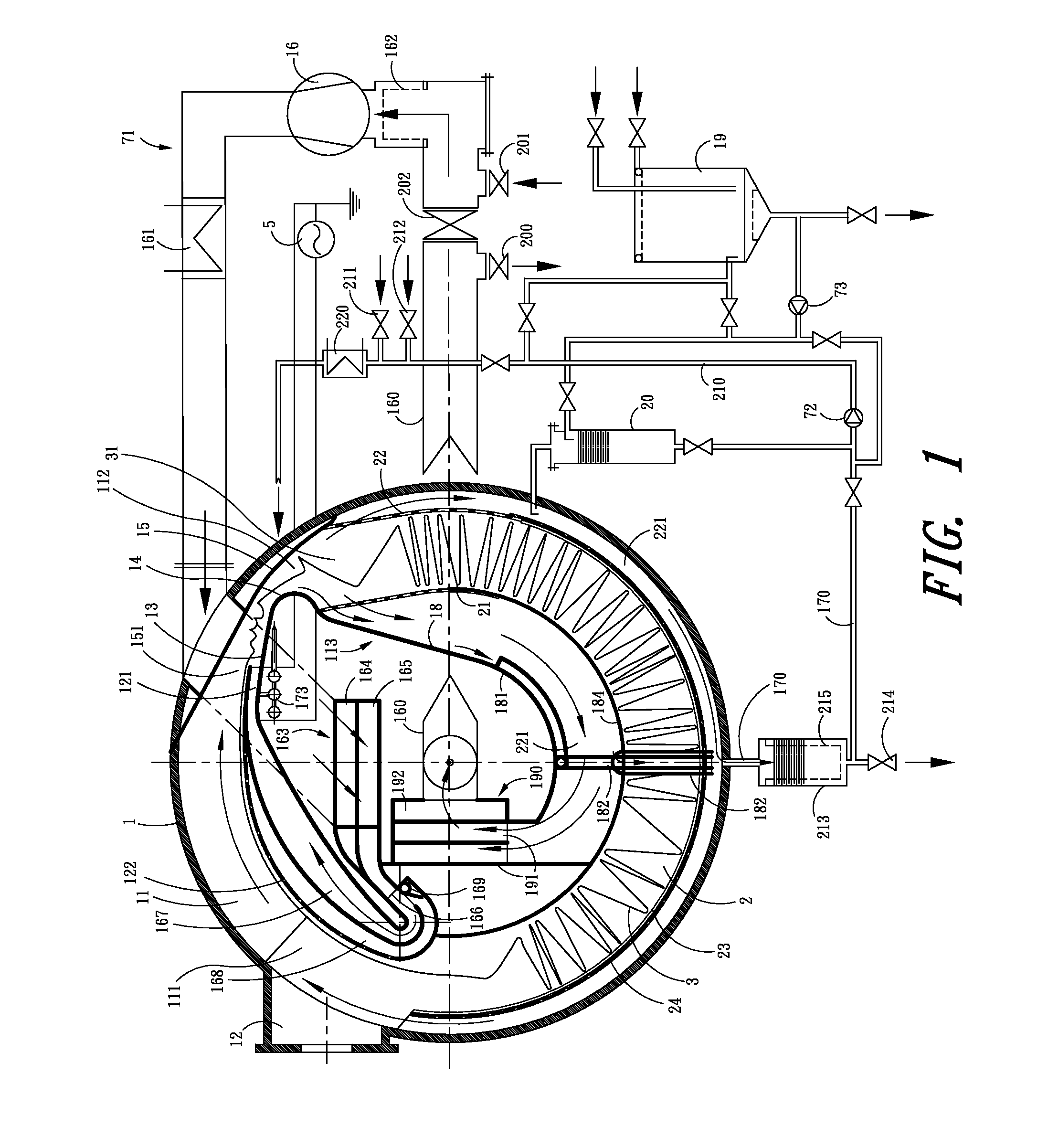
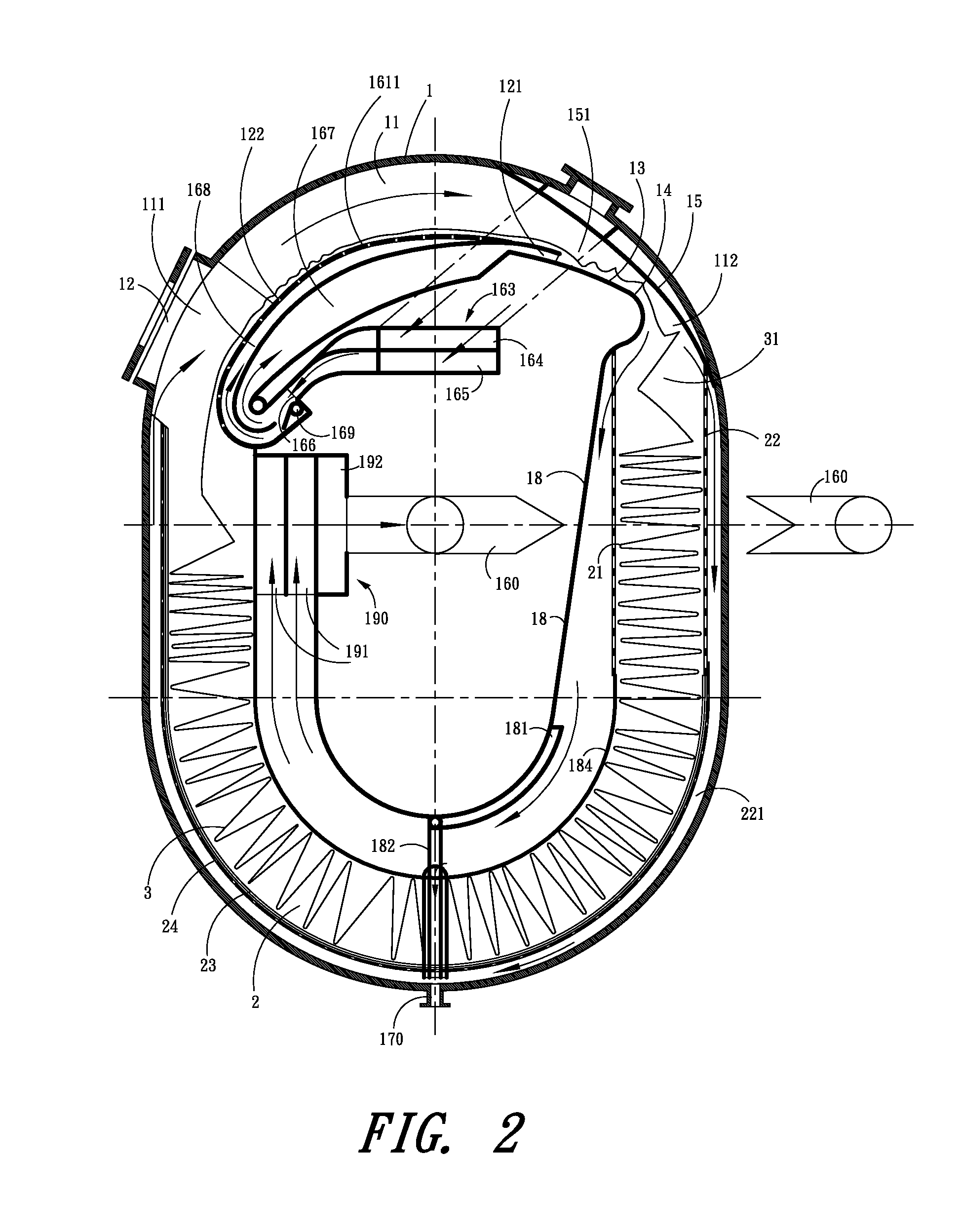
[0053]Please see FIGS. 1 to 7, which illustrate the impulse type shock wave flash dyeing machine of the present invention. The dyeing machine of the present invention includes the following parts and components: a processing tank 1, fabric accumulator 2, fibrous fabric 3, fabric guiding tube 11, doorway 12, reflective motion plate 13, U-shaped circumrotating plate 14, direction guiding plate 15, blower 16, fluid gathering plate 18, reserve tank 19, pump-less content adding device 20, inner separating net barrier 21, outer separating net barrier 22, slider 23, net-holed plate 24, upstream fabric flop portion 31, a row of slits 42, entry 43, backflow entrance 46, arc-shaped distributing tube portion 61, tube 62, air transporting pipeline 71, circulation pump 72, content adding pump 73, upstream inlet 111, downstream outlet 112, a row of joint nozzles 121, air nozzles 122, narrow passage 151, air backflow tube 160, air heat exchanger 161, air filtering unit 162, air cross flow distribu...


PUM


Abstract

An impulse type shock wave flash dyeing machine is disclosed. A row of joint nozzles can send out high-speed air flows to prompt fibrous fabric to spread out and move in the dyeing machine through the effect of impulse. Dyes or processing agents may be converted into fine mist and is carried by the high-speed air flows to blast the fibrous fabric (3). Therefore, the dyes or processing agents can enter the fibrous fabric (3) quickly and can diffuse or spread out in the fibrous fabric (3) swiftly through strong elastic and inelastic collisions as well as the effect of shock wave. Such collisions and effect can impart enough energy to the dyes or processing agents and convert non-activated molecules into activated molecules. In addition, the effect of corona discharge may be used to generate high-energy particles and hence the goals of clean and swift processes may be achieved.

Description

BACKGROUND OF THE INVENTION[0001]1. Field of the Invention[0002]The invention relates to an impulse type shock wave flash dyeing machine, which is abbreviated as a shock wave dyeing machine. The dyeing machine of the present invention is an improved version of the spray dyeing apparatus with breadth expansion and vibration-enhanced dyeing operation and is a machine that may be used to carry out the dyeing process and other processes and that is characterized with high efficiency, multiple functions, multiple applications and environmental friendliness.[0003]2. Description of the Prior Art[0004]To slow down the global warming and climate change, many processing technologies have been used in the processing of fibrous fabric. These technologies include shock wave technology, electrochemistry, low-temperature plasma technology, carbon dioxide supercritical fluid technology, biological enzyme technology, supersonic technology, radioactive energy technology, microwave technology, etc. Th...

Claims


Application Information

Patent Timeline
IPC IPC(8): D06B3/28
CPCD06B3/28
Inventor JIANG, ZHAO-CHENG
Owner ZHAO CHENG JIANG
Learn More