Method for producing a metal component

a metal component and metal technology, applied in the direction of machining electric circuits, electrical machining apparatus, electric circuits, etc., can solve the problems of greater problems and relatively poor machinability of nickel alloy components, and achieve the effect of superior component sections and difficult machinability of component materials

Inactive Publication Date: 2012-02-02
LEISTRITZ TURBOMASCHEN TECHN
View PDF0 Cites 4 Cited by
  • Summary
  • Abstract
  • Description
  • Claims
  • Application Information

AI Technical Summary

Benefits of technology

[0004]The problem addressed by the invention is therefore to specify a method which is intended for machining a metal component and makes possible f

Problems solved by technology

Whereas this is often straightforwardly possible in the case of large metal components on account of the accessibility of the superior component sections which are to be finish-machined, problems often arise in particular with smaller metal components or with metal components in which the superior component sections are either very narrow or are difficult to reach on account of the component geometry, since the tool can be guided into the desired

Method used


Image

  • Method for producing a metal component
  • Method for producing a metal component
  • Method for producing a metal component

Examples


Embodiment Construction

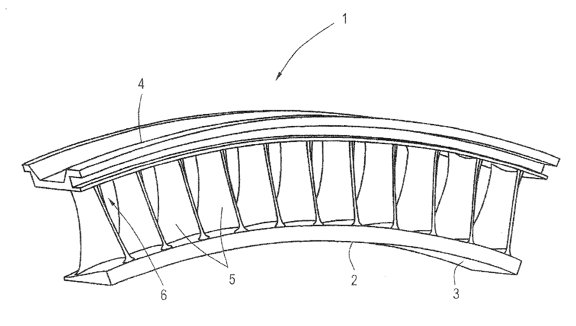
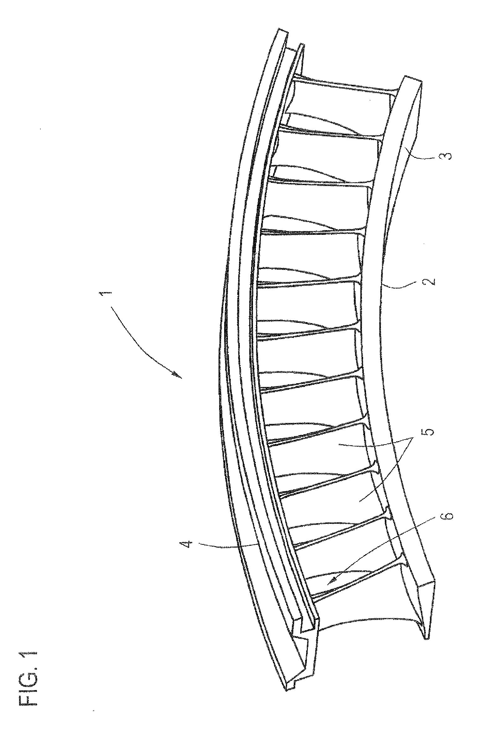
[0027]FIG. 1 shows, in the form of a perspective view, a metal component 1 in the form of a guide vane cluster 2 which for the purpose of forming a complete ring, is assembled with a plurality of such clusters to give a ring shape. Such a guide vane cluster consists of two shrouds 3, 4 and a multiplicity of airfoils 5 extending between said shrouds 3, 4. The shrouds 3, 4 and the airfoils 5 are fashioned from solid material by cutting and / or other removal processes. The airfoils 5 have a complexly twisted geometry and are very closely spaced apart, i.e. there are only very narrow spaces 6 between the individual airfoils 5. The complex geometry consequently results in curved edge regions and curved surfaces in the transition between the airfoils 5 and the shrouds 3, 4 or at the surfaces of the shrouds 3, 4 and at the surfaces of the airfoils 5 themselves, which, after the metal component 1 or its sections (shrouds 3, 4, airfoils 5) have been pre-machined using appropriate working proc...


PUM

PropertyMeasurementUnit
Flow rateaaaaaaaaaa
Flow rateaaaaaaaaaa
Shapeaaaaaaaaaa

Abstract

Method for machining a metal component which has a three-dimensional shape produced by removing and/or shaping material, wherein one or more superior component sections are electrochemically finish-machined by means of a nozzle-like cathode, via which an electrolyte is delivered into the working region, and wherein the cathode or the metal component is moved freely in space by means of a manipulator element.

Description

[0001]This application claims priority to German Patent Application No. 1020010032701.8 filed Jul. 29, 2010, the contents of which are incorporated herein by reference.BACKGROUND OF THE INVENTION[0002]The invention relates to a method for machining a metal component which has a three-dimensional shape produced by removing and / or shaping material.[0003]Metal components are machined or shaped using various methods in order to obtain a desired three-dimensional geometry. Material-removing methods such as, for example, drilling, turning, milling, EDM (electrical-discharge machining) and ECM (electrochemical machining) or material-shaping methods such as, for example, stamping, pressing or forging are known. These methods normally serve for rough contouring, i.e. the three-dimensional shape is substantially fashioned by these working processes. Superior component sections, however, still have to be subjected to finish machining in order for any burrs, projections, edges, corners and the ...

Claims


Application Information

Patent Timeline
IPC IPC(8): C25F3/16C25F7/00
CPCB23H11/00B23H3/00
Inventor ROEBLITZ, MARTINSCHMIDT, GEORG
Owner LEISTRITZ TURBOMASCHEN TECHN
Why Eureka
Try Eureka