Laser-Assisted Material Phase-Change and Expulsion Micro-Machining Process

a technology of phase change and expulsion, applied in the field of microelectromechanical systems, can solve the problems of affecting the application of these parts and previously unattainable features, and achieve the effect of high-aspect ratio (10:1) features and rapid production of small lateral features

Pending Publication Date: 2021-05-13
MASSACHUSETTS INST OF TECH
View PDF5 Cites 2 Cited by
  • Summary
  • Abstract
  • Description
  • Claims
  • Application Information

AI Technical Summary

Benefits of technology

[0010]The present invention relates to a laser micro-machining process called laser-assisted material phase-change and expulsion (LAMPE) micromachining. In addition, the present invention relates to a novel MEMS fabrication process called multi-lamina assembly of laser-micro-machined laminates (MALL) to fabricate MEMS. In the MALL process, first, the individual layers of a micro-electromechanical system (MEMS) are fabricated using the LAMPE micro-machining process. Next, the fabricated microstructure laminates are stack assembled and bonded to fabricate MEM systems. The MALL MEMS fabrication process enables greater material section and integration, greater design flexibility, low-cost manufacturing, rapid development, and integrated packaging.
[0012]A further object of the invention is an electro-deburring process for removing micro-burrs from LAMPE micro-machined or laser micro-machined metal parts. These micro-burrs are formed due to solidification of melted metal during laser micromachining and hinders the application of these parts in fabricating micro-electromechanical system (MEMS). The disclosed process and its application remove these burrs and produces clean parts suitable for MEMS fabrication that are comparable to parts produced using a conventional deep reactive ion etching (DRIE) process. Further disclosed is the application of an electro-deburring process to deburr metal parts produced using a micro-milling process, thereby, also enabling their application in MEMS fabrication.

Problems solved by technology

Such features were previously not achievable using conventional laser micromachining process.
These micro-burrs are formed due to solidification of melted metal during laser micromachining and hinders the application of these parts in fabricating micro-electromechanical system (MEMS).

Method used


Image

  • Laser-Assisted Material Phase-Change and Expulsion Micro-Machining Process
  • Laser-Assisted Material Phase-Change and Expulsion Micro-Machining Process
  • Laser-Assisted Material Phase-Change and Expulsion Micro-Machining Process

Examples


Embodiment Construction

1 Laser-Assisted Material Phase-Change & Expulsion (LAMPE) Micro-Machining

1.1 Introduction

[0058]Enabling MEMS fabrication using metals is advantageous because they offer a wide range of mechanical and electrical properties. Moreover, these properties can be tuned by the alloying process. The ability to fabricate MEM systems using metals empowers a new paradigm in MEMS design. Moreover, the metal foils used for MEMS fabrication are low-cost and easy to fabricate using a roll forming process [61]. Unfortunately, the existing wet and dry etching processes are isotropic and not suitable for fabricating high aspect ratio microstructures required for making MEMS.

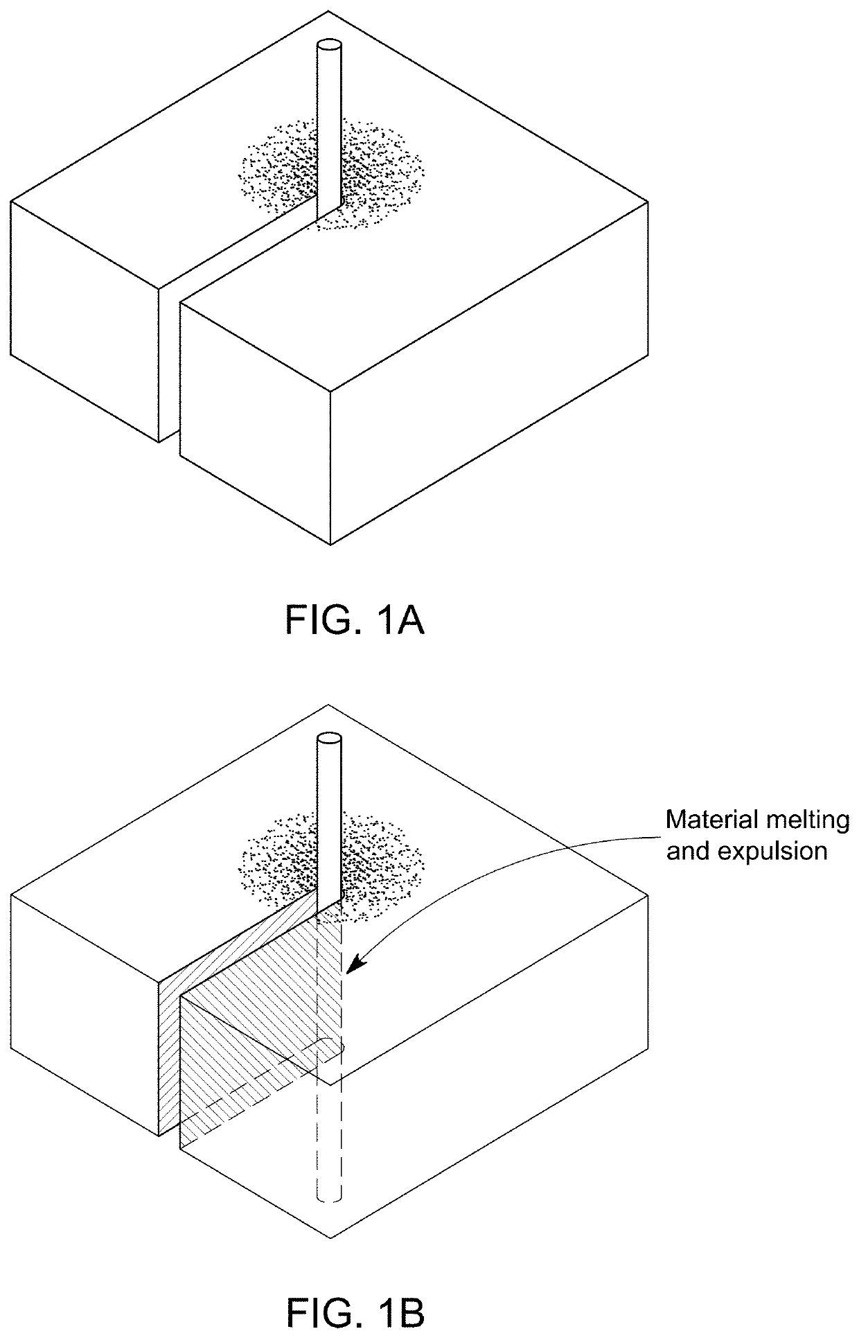
[0059]At a macro-scale, lasers are widely used for cutting metal sheets. In this process, a laser is used to melt the metal, and a high-pressure air jet is used to expel the melted material. However, high-pressure jets cannot be employed at a micro-scale due to the delicate nature of the laser micro-machined structures. For this r...


PUM

PropertyMeasurementUnit
effective energyaaaaaaaaaa
focal lengthaaaaaaaaaa

Abstract

A laser micro-machining process called laser-assisted material phase-change and expulsion (LAMPE) micromachining that includes cutting features in a cutting surface of a piece of material using a pulsed laser with intensity, pulse width and pulse rate set to melt and eject liquid material without vaporizing said material, or, in the case of silicon, create an ejectible silicon oxide. Burrs are removed from the cutting surface by electro-polishing the cutting surface with a dilute acid solution using an electric potential higher than a normal electro-polishing electric potential. A multi-lamina assembly of laser-micro-machined laminates (MALL) may utilize MEMS. In the MALL process, first, the individual layers of a micro-electromechanical system (MEMS) are fabricated using the LAMPE micro-machining process. Next, the fabricated microstructure laminates are stack assembled and bonded to fabricate MEM systems. The MALL MEMS fabrication process enables greater material section and integration, greater design flexibility, low-cost manufacturing, rapid development, and integrated packaging.

Description

[0001]This application is related to, and claims priority from U.S. Provisional Patent Application No. 62 / 932,914 filed Nov. 8, 2019. Application 62 / 932,914 is hereby incorporated by reference in its entirety.BACKGROUNDField of the Invention[0002]The present invention relates generally to the field of micro-electromechanical systems (MEMS), and more particularly to a laser-assisted micro-machining process.Description of the Problem Solved[0003]Micro-electromechanical systems (MEMS) have many applications in fields like healthcare, consumer electronics, automobiles, and energy. However, the development of novel MEMS devices has been significantly hindered by several limitations of lithography-based microfabrication processes used to manufacture MEMS. First, these processes require access to expensive microfabrication tools such as photolithography systems, mask aligners, and deposition and etching tools. Moreover, these processes have a lengthy process development time. The high cost...

Claims


Application Information

Patent Timeline
Patent Type & Authority Applications(United States)
IPC IPC(8): B81C1/00B23K26/00B23K26/354
CPCB81C1/00547B81C1/00611B81C1/00904B23K26/0006B23K2101/40B81C2201/0125B81C2201/0143B81C2203/032B81C2203/054B23K26/354B23K2103/50B23K26/38B23K26/402B23K26/0622B23K26/082B23K26/382B81C1/00531
Inventor PATIL, PRASHANT
Owner MASSACHUSETTS INST OF TECH
Why Eureka
Try Eureka