Electrochromic window fabrication methods

a technology of electrochromic windows and fabrication methods, applied in the direction of static indicating devices, door/window protective devices, instruments, etc., can solve the problem of limited size of electrochromic windows, and achieve the effect of maximizing the efficient use of glass sheets

Active Publication Date: 2012-02-02
VIEW INC
View PDF3 Cites 423 Cited by
  • Summary
  • Abstract
  • Description
  • Claims
  • Application Information

AI Technical Summary

Benefits of technology

[0010]A method of manufacturing one or more electrochromic panes may be characterized by the following operations: (a) fabricating an electrochromic device on a glass sheet; (b) defining a cutting pattern for cutting the glass sheet in order to create the one or more electrochromic panes, the cutting pattern defined, at least in part, by characterizing the glass sheet and / or electrochromic device by one or more physical features (characteristics) after fabrication of the electrochromic device; and (c) cutting the glass sheet according to the cutting pattern to create the one or more electrochromic panes. In one embodiment, characterizing the glass sheet and / or electrochromic device includes identifying the one or more low-defectivity areas, scribing one or more isolation trenches near one or more edges of the glass sheet, applying a temporary bus bar to the electrochromic device, and activating the electrochromic device in order to evaluate the electrochromic device for defectivity. Other methods of identifying defects, including areas of non-uniformity, in the EC device include application of polarized light to the glass pane and the like. In one embodiment, mapping data sets are created based on the one or more low-defectivity areas and / or non-uniform areas on the electrochromic device and the data sets are compared in order to maximize efficient use of the glass sheet.

Problems solved by technology

If the leakage current is higher than a threshold or the resistivity of a TCO layer is higher than a threshold, the size of the electrochromic panes is limited to ensure that the resulting windows perform adequately in spite of the device's high leakage or the TCO's high resistivity.

Method used


Image

  • Electrochromic window fabrication methods
  • Electrochromic window fabrication methods
  • Electrochromic window fabrication methods

Examples


Embodiment Construction

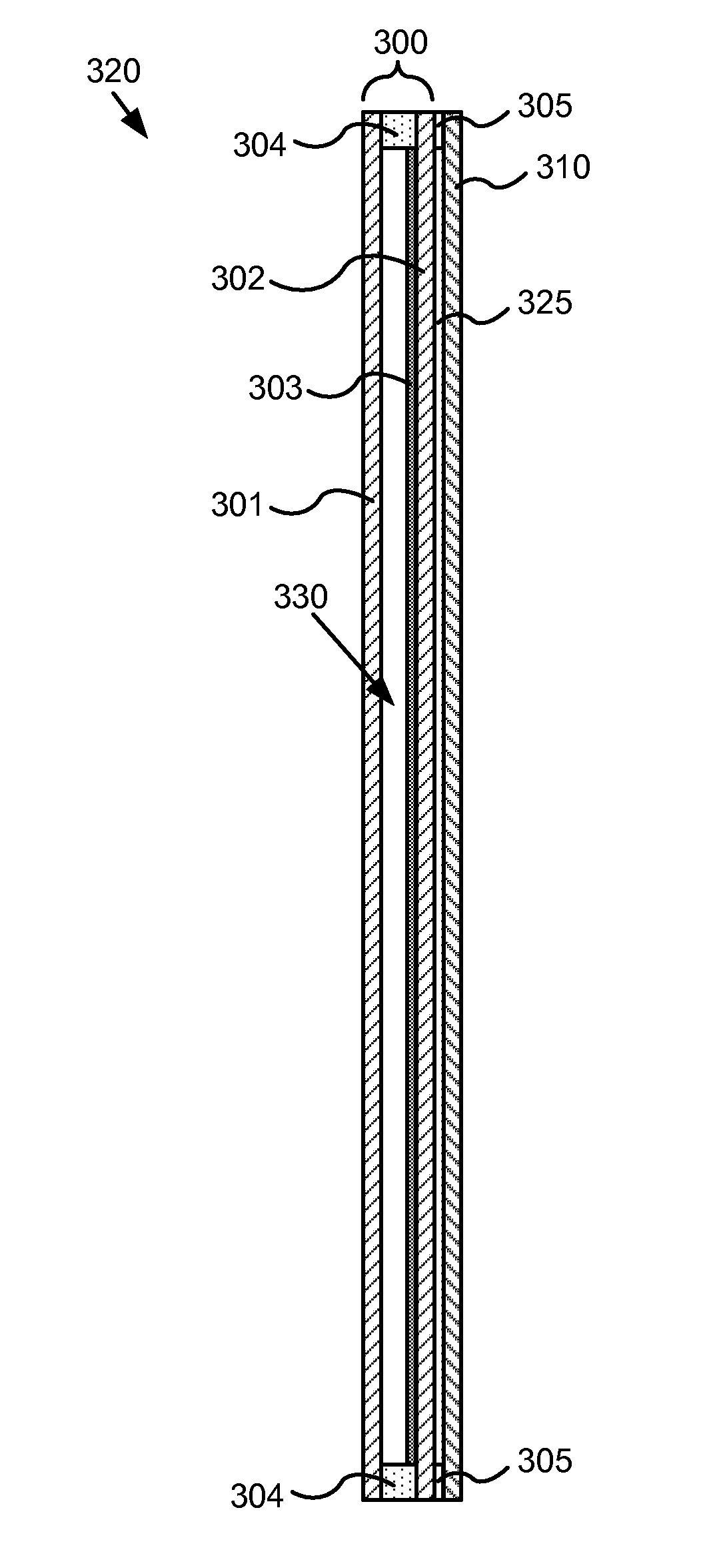
[0022]For window applications, it is important that electrochromic panes be both strong and relatively free of defects. Conventionally, glass panes are strengthened by tempering. Unfortunately, the tempering process can introduce defects in an electrochromic device. Hence, most efforts to produce electrochromic windows employ a fabrication sequence of first cutting a glass pane to size, then tempering the glass, and finally forming the electrochromic device on the tempered window pane. The electrochromic device is typically formed by depositing a sequence of thin layers on one side of the pre-cut and tempered glass pane. Unfortunately, the described sequence of cutting and then forming the EC device frequently gives rise to some low quality electrochromic windows because modern fabrication processes often produce one or more visible defects on an electrochromic device. Of course, the manufacturer may refuse to tolerate low quality devices, but rejection of low quality panes correspo...


PUM

PropertyMeasurementUnit
perimeteraaaaaaaaaa
perimeteraaaaaaaaaa
lengthaaaaaaaaaa

Abstract

Methods of manufacturing electrochromic windows are described. An electrochromic device is fabricated to substantially cover a glass sheet, for example float glass, and a cutting pattern is defined based on one or more low-defectivity areas in the device from which one or more electrochromic panes are cut. Laser scribes and / or bus bars may be added prior to cutting the panes or after. Edge deletion can also be performed prior to or after cutting the electrochromic panes from the glass sheet. Insulated glass units (IGUs) are fabricated from the electrochromic panes and optionally one or more of the panes of the IGU are strengthened.

Description

FIELD OF INVENTION[0001]The invention relates generally to electrochromic devices, more particularly to electrochromic windows.BACKGROUND[0002]Electrochromism is a phenomenon in which a material exhibits a reversible electrochemically-mediated change in an optical property when placed in a different electronic state, typically by being subjected to a voltage change. The optical property is typically one or more of color, transmittance, absorbance, and reflectance. One well known electrochromic material is tungsten oxide (WO3). Tungsten oxide is a cathodic electrochromic material in which a coloration transition, transparent to blue, occurs by electrochemical reduction.[0003]Electrochromic materials may be incorporated into, for example, windows for home, commercial and other uses. The color, transmittance, absorbance, and / or reflectance of such windows may be changed by inducing a change in the electrochromic material, that is, electrochromic windows are windows that can be darkened...

Claims


Application Information

Patent Timeline
Patent Type & Authority Applications(United States)
IPC IPC(8): G02F1/153B32B38/04B32B37/02H05K3/00
CPCB32B17/10055B32B17/10128B32B17/10183B32B17/10513B32B17/10697Y10T156/1062B32B17/1099B32B2333/12G02F1/153Y10T29/49124Y10T156/1052B32B17/10908Y10T29/49004E06B3/6722E06B9/24E06B2009/2464E06B3/673G02F1/1533G02B1/14G02F1/133311G02F1/133308G02F1/155G02F1/161
Inventor COLLINS, MARK A.PARKER, RONALD M.ROZBICKI, ROBERT T.SHRIVASTAVA, DHAIRYA
Owner VIEW INC
Why Eureka
Try Eureka