
Low-Aspect Ratio Carbon Nanostructures

a carbon nanostructure, low-aspect ratio technology, applied in the field of nanotechnology, can solve the problems of difficult to make very low l/d ratio, inability to grow by existing techniques, and uneven length of such cnts

Inactive Publication Date: 2012-02-02
NORTHEASTERN UNIV
View PDF8 Cites 21 Cited by
  • Summary
  • Abstract
  • Description
  • Claims
  • Application Information

AI Technical Summary

Benefits of technology

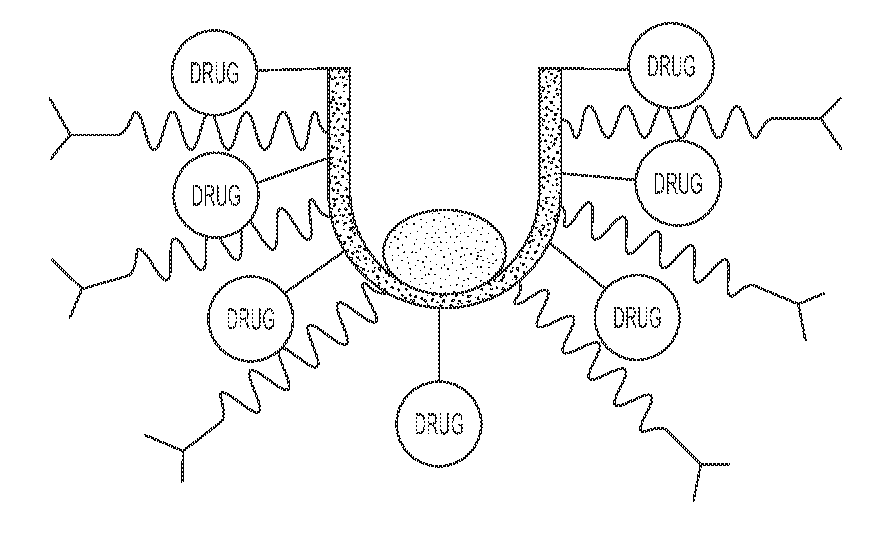
"The invention is about a new process for making nanostructures with low aspect ratios (less than 10) and continuous lateral walls. These nanostructures can have a length, transverse diameter, and interior space that make them suitable for various applications such as drug delivery, imaging, and sensing. The process involves using a hollow nanocup with a lateral wall that has a thickness of about 1 nm to about 20 nm. The nanostructures can also contain other agents such as therapeutic agents or detection agents. The invention also includes an array of nanostructures comprising a plurality of nanocups."

Problems solved by technology

(1997) Appl. Phys. Lett. 71:2629-2631) have been impossible to grow by existing techniques due to the difficulty in controlling and terminating growth during initial stages.
For example, it is very difficult to make very low L / D ratio (it has been report only down to 10, L / D ratio) and the length of such CNTs is not uniform.
Additionally, it is difficult to control the L / D ratio, diameter, and length of such nanotube structures.
However, current technologies are significantly limited by the difficulty of tailoring morphology and aspect ratio of individual nanoscale units.

Method used


Image

  • Low-Aspect Ratio Carbon Nanostructures
  • Low-Aspect Ratio Carbon Nanostructures
  • Low-Aspect Ratio Carbon Nanostructures

Examples


example 1

Preparation of Low-Aspect Ratio Carbon Nanostructures

A. Methods

[0158]Fabrication of Anodized Aluminum Oxide (AAO) Template

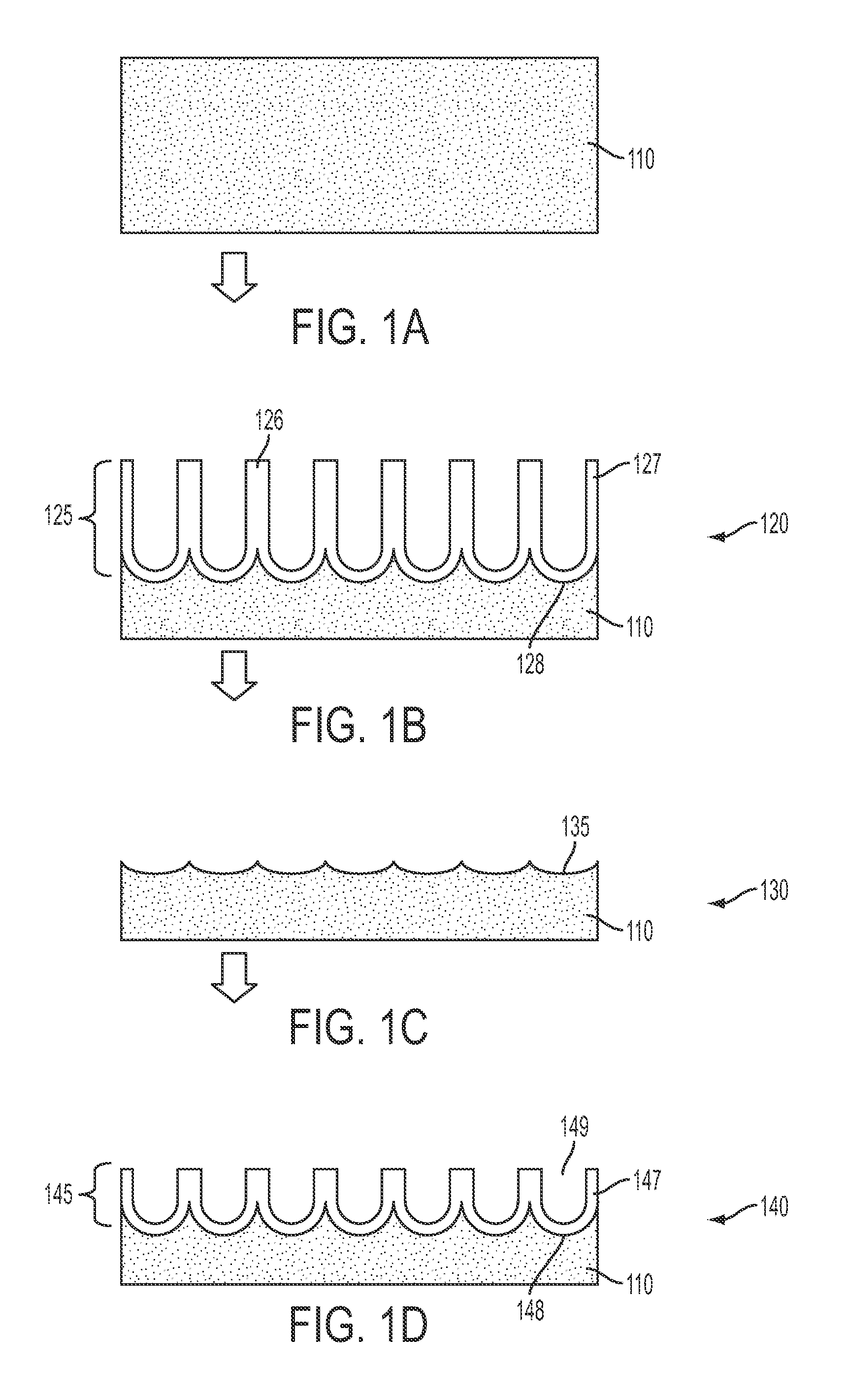
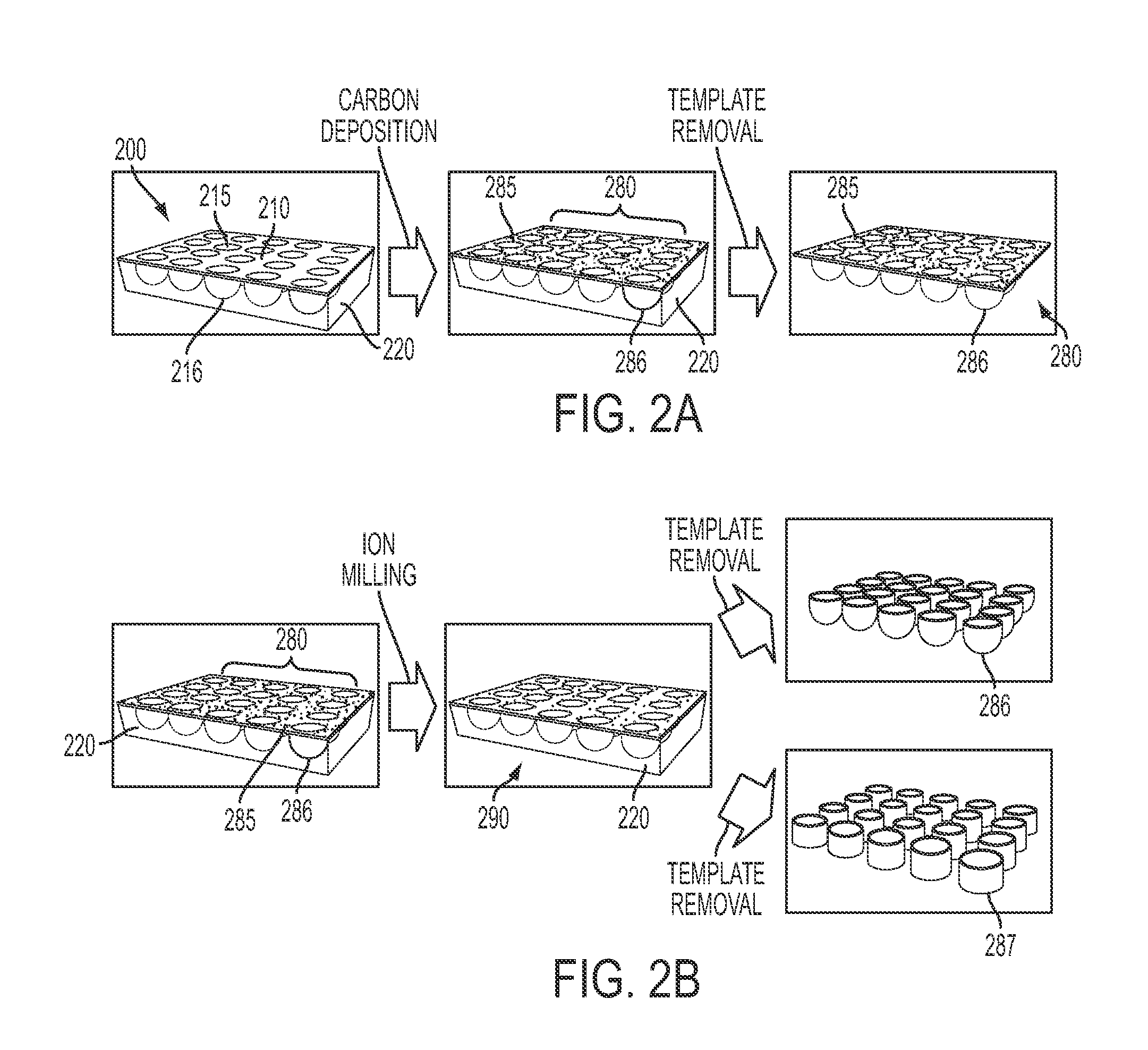
[0159]In order to produce highly ordered arrays of nanopores, a two-step anodization process was used. In the first step, a high purity Al foil (Alfa Aesar, 99.99%) was anodized at 40-45V for 4 hours in 3-5% oxalic acid (C2H4O2) solution at room temperature (RT). The anodized Al film was placed in the solution containing a mixture of 5% phosphoric (H3PO4) and 5% chromic (H2CrO4) acids for 24 hours to remove the formed aluminum oxide layer. This process resulted in the formation of a well-ordered array of scallop-shapes on the aluminum surface.

[0160]A re-anodization process was then performed but in precisely controlled and short time (for 20 sec to 40 sec) to fabricate highly organized short nanochannels (80 nm-200 nm in length) giving 103-105 time smaller L / D aspect ratio. Then, samples were soaked in a 5% phosphoric acid solution for 1 hour, which resulted in t...


PUM

PropertyMeasurementUnit
lengthaaaaaaaaaa
transverse diameteraaaaaaaaaa
thicknessaaaaaaaaaa

Abstract

Low-aspect ratio nanostructures, such as nanocups, nanorings, and arrays of nanocups and nanorings, methods of fabrication of nanostructures, and methods of using nanostructures are disclosed.

Description

CROSS-REFERENCE TO RELATED APPLICATIONS[0001]This application claims the benefit of priority to U.S. Provisional Application No. 61 / 159,289, filed Mar. 11, 2009, the contents of which are incorporated by reference herein in their entirety.FIELD OF THE INVENTION[0002]The invention is in the field of nanotechnology including nano-medicine and nano-metrology.BACKGROUND OF THE INVENTION[0003]Short structures, including very short nanotubes (Lu et al. (1996) Carbon 34:814-816; Shelimov et al. (1998) Chem. Phys. Lett. 282:429-434; Liu et al. (1998) Science 280:1253-1256; Liesbeth et al. (1997) Appl. Phys. Lett. 71:2629-2631) have been impossible to grow by existing techniques due to the difficulty in controlling and terminating growth during initial stages.[0004]Currently, short carbon nanotubes (“CNTs”) are fabricated by cutting longer CNTs (micron scale) using acid based chemical treatments. Such chemically shortened CNTs have many disadvantages. For example, it is very difficult to mak...

Claims


Application Information

Patent Timeline
Patent Type & Authority Applications(United States)
IPC IPC(8): A61K49/00A61K9/00A61K33/00B05D5/00H01J37/31B32B1/00C23C16/26B82Y5/00B82Y40/00
CPCY10T428/13B82Y40/00C01B2202/08C01B2202/10C01B2202/34C01B2202/36C01B32/16C01B32/18
Inventor JUNG, YUNG JOONCHUN, HYUNKYUNGMENON, LATIKA
Owner NORTHEASTERN UNIV
Learn More