
Arrangement and method for generating hydrogen from hydrocarbon fuel

a technology of hydrocarbon fuel and arrangement and method, which is applied in the direction of electrochemical generators, hydrogen separation using liquid contact, instruments, etc., can solve the problems of increasing the cost of fuel, major problems for all catalysts in the system, and the conversion of aromatic compounds and long chained carbon compounds comprised in liquid hydrocarbon fuel, etc., to achieve easy replacement, reduce the number of reactors needed, and simplify the clean-up process

Active Publication Date: 2012-02-02
POWERCELL SWEDEN AB
View PDF6 Cites 33 Cited by
  • Summary
  • Abstract
  • Description
  • Claims
  • Application Information

AI Technical Summary

Benefits of technology

[0004]The water-gas shift reaction (WGS) is a chemical reaction in which carbon monoxide reacts with water to form carbon dioxide and hydrogen:CO+H2O→CO2+H2 Thereby, the carbon monoxide amount in the hydrogen rich gas produced by the fuel reformer can be reduced.
[0027]By using the inventive arrangement, the sulphur trap and a high temperature water-gas shift reactor can be replaced by the molten salt reactor, whereby the cleanup process of the hydrogen rich gas can be simplified.

Problems solved by technology

They pose major problems for all catalysts in the system, i.e. the catalysts used for reforming as well as the catalysts in the fuel cell.
The removal of sulphur from liquid hydrocarbons down to the aforementioned levels is not trivial and requires severe process conditions, especially for the desulphurization of diesel, which increases the costs for the fuel.
A further problem in the current reformer technology is the conversion of aromatic compounds and long chained carbon compounds comprised in the liquid hydrocarbon fuel.
Usually, it is not possible to convert the aromatic compounds and long chained carbon compounds in the reformer completely to the hydrogen rich gas, namely hydrogen, carbon dioxide, carbon monoxide, and water, so that the hydrogen rich gas leaving the reformer also comprises unconverted fuel compounds, the so-called fuel slip.
This fuel slip is a problem for subsequent clean-up steps of the gas from sulphur compounds and other inorganic compounds since this fuel slip will act as a poison for the fuel cell downstream of the clean-up process.
Disadvantageously, this method does not provide a total removal of the fuel slip and lowers the total efficiency of the system.
Further, the fuel slip due to its poisoning character contributes to an unwanted premature aging of the fuel cell exposed to it.

Method used


Image

  • Arrangement and method for generating hydrogen from hydrocarbon fuel
  • Arrangement and method for generating hydrogen from hydrocarbon fuel

Examples


Embodiment Construction

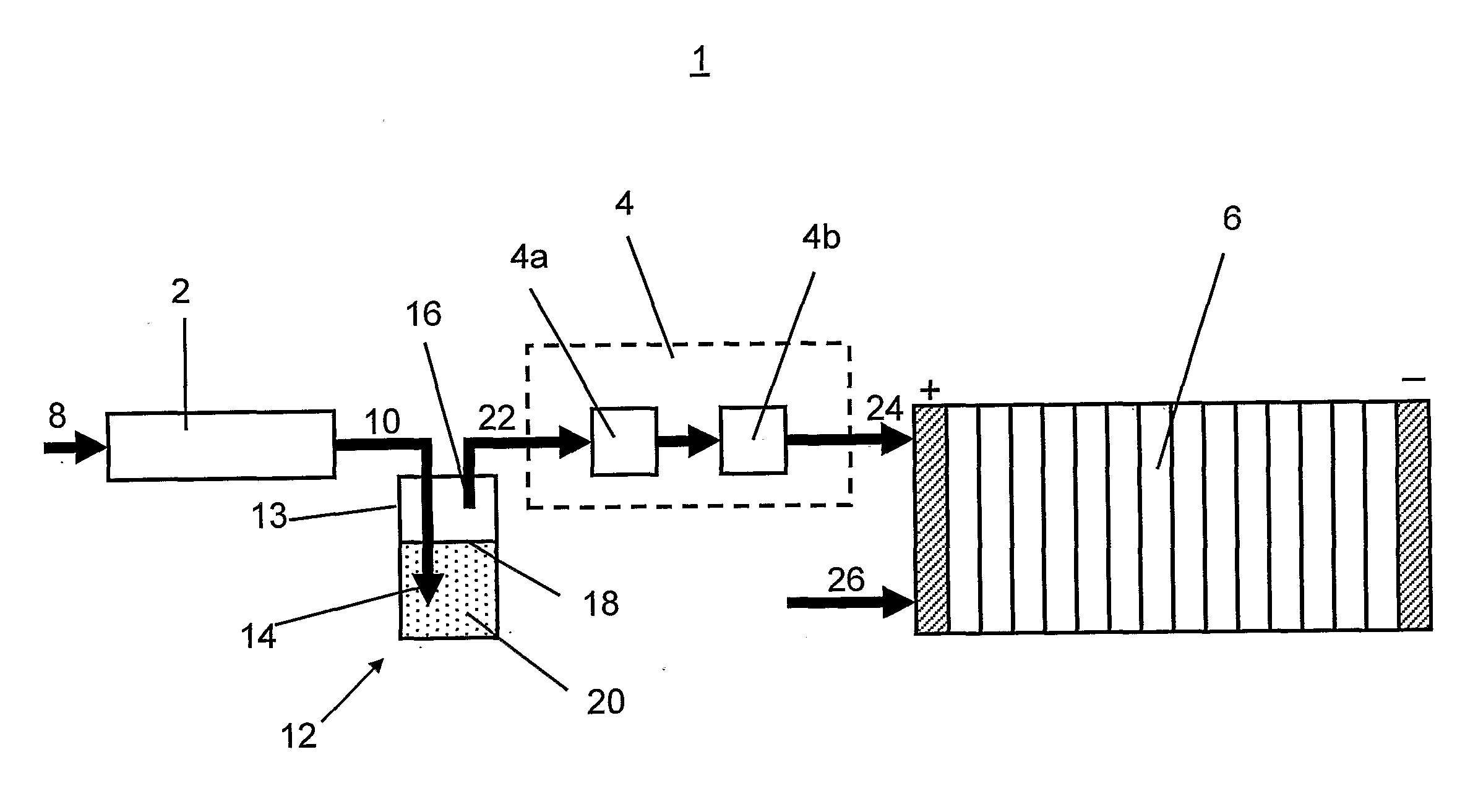
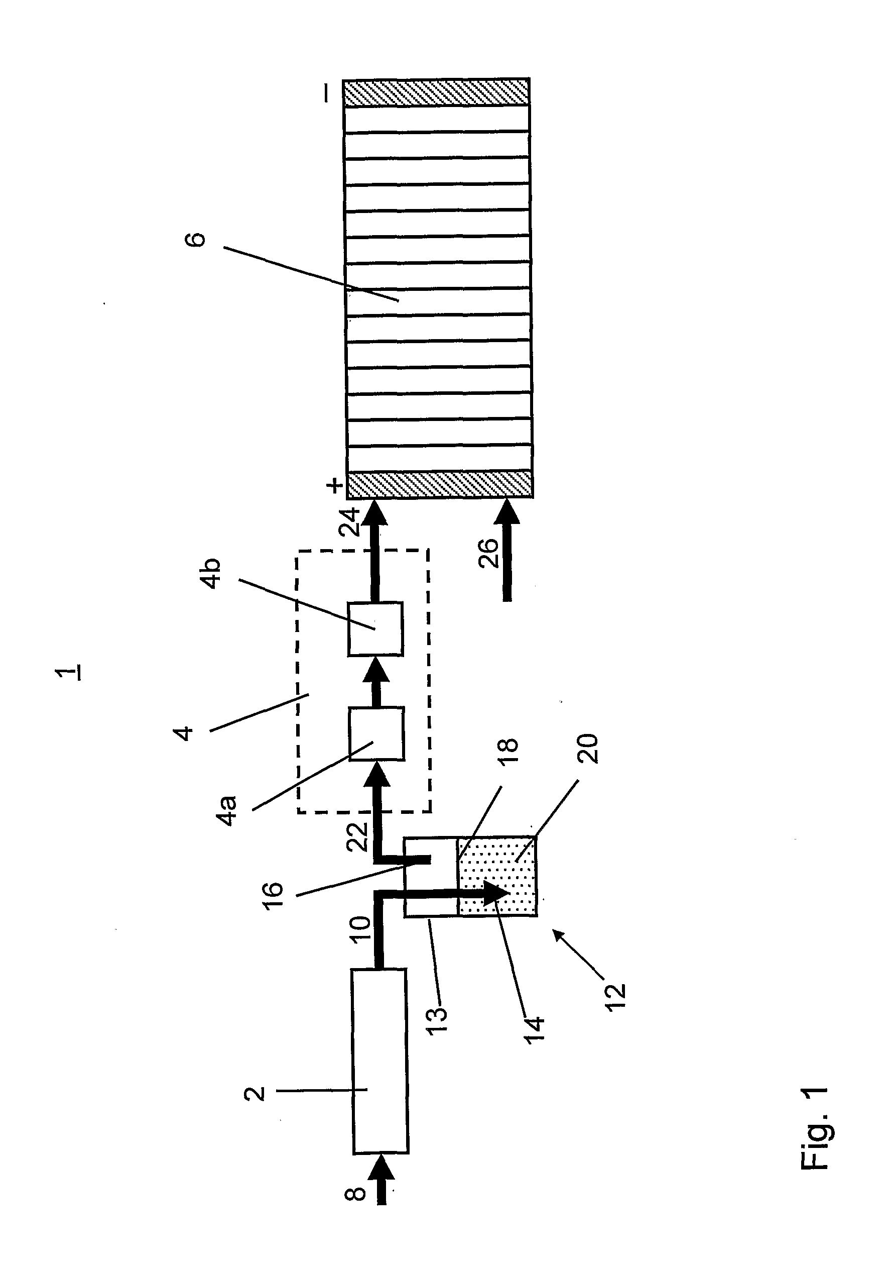
[0032]FIG. 1 shows a schematic drawing of a preferred embodiment of the inventive arrangement for generating hydrogen from hydrocarbon fuel as used in an APU system. In principal, an APU system 1 comprises a fuel reformer 2, a gas clean-up system 4 and a fuel cell 6. The fuel reformer 2 produces hydrogen rich gas 10 from hydrocarbon fuel 8, which is cleaned from unwanted by-products, such as sulphur and / or carbon monoxide in the gas clean-up reactor 4. The cleaned hydrogen rich gas 24 is then fed to the fuel cell 6 which in turn generates electric energy. These APU systems provide trucks, boats or other vehicles with electrical power for instance in situations when the main engine is off, as for example, when the truck is parked since the driver has to take a rest during the night. Dependent on what kind of fuel cell is used—low or high temperature fuel cells—the hydrogen rich gas 10 produced by reformer 2 has to pass through different cleaning steps for removing sulphur compounds a...


PUM


Abstract

An arrangement and a method are provided for generating hydrogen from hydrocarbon fuel, wherein hydrocarbon fuel is supplied to a fuel reformer for producing hydrogen rich gas including hydrogen, carbon monoxide and possibly unconverted fuel compounds, wherein the amount of carbon monoxide and / or the unconverted fuel compounds is reduced with the help of a molten salt reactor arranged downstream the fuel reformer. An auxiliary power unit including such an arrangement is also provided.

Description

BACKGROUND AND SUMMARY[0001]The present invention relates to an arrangement and a method for generating hydrogen from hydrocarbon fuel. The arrangement comprises a fuel reformer for reforming hydrocarbon fuel to a hydrogen rich gas comprising at least hydrogen, carbon monoxide and possibly unconverted fuel compounds. The hydrogen gas produced according to the present invention can advantageously be used to operate fuel cells. The present invention also relates to an auxiliary power unit (APU) comprising such an arrangement.[0002]The conversion of hydrocarbon fuels to a hydrogen rich product gas is a central process step in fuel processors as for instance those used in APU systems. APU systems can advantageously be used in vehicles of all kinds as well as in other applications which have a need for off-grid generation of electricity from a main fuel source. For vehicle power trains, liquid or gaseous hydrocarbon fuels like gasoline, kerosene and diesel, but also biogas or other biofu...

Claims


Application Information

Patent Timeline
IPC IPC(8): H01M8/06B01J7/00
CPCC01B3/348C01B3/48C01B2203/0233C01B2203/0261C01B2203/0288C01B2203/0485C01B3/52C01B2203/146C01B2203/147H01M8/0612Y02E60/50C01B3/34C01B2203/142C01B2203/066Y02P20/129
Inventor BODEN, ANDREASLINDBERGH, GORAN
Owner POWERCELL SWEDEN AB
Learn More