
Porous electroactive hydrogels and uses thereof

a technology of electroactive hydrogels and electroactive hydrogels, which is applied in the field of porous electroactive hydrogels, can solve the problems of not being able to contribute to the permanent network elasticity, chemical hydrogels are not homogeneous, and chain loops and free chain ends also produce network defects in both physical and physical, so as to achieve fast contractility, maximize electroactuation, and be able to bend more easily

Active Publication Date: 2012-02-02
PRESIDENT & FELLOWS OF HARVARD COLLEGE
View PDF2 Cites 50 Cited by
  • Summary
  • Abstract
  • Description
  • Claims
  • Application Information

AI Technical Summary

Benefits of technology

[0007]The present invention provides a solution to earlier limitations of electroactive hydrogels. The present invention provides electroactive polymer hydrogels which, among other things, contract fast and are able to bend more easily and to a larger extent as compared to the prior art hydrogels. The electroactive polymer hydrogels of the present invention have been engineered to maximize electroactuation by incorporating porous scaffolds in the hydrogels. Without intending to be limited by theory, it is believed that the porosity in the hydrogels of the present invention decreases the cross-sectional area of the hydrogel, such that the hydrogel requires less COOH groups on the anode side of the hydrogel to produce a bending motion. In addition, the porosity decreases the Young's modulus of the hydrogels and enhances the deswelling and mechanical properties to further improve the actuation of these hydrogels. The improved electroactive hydrogels provided herein are durable, responsive, and suitable for use in a clinical setting, e.g., suitable for use as artificial muscle constructs, as well as for use in non-clinical applications such as use as soft robotic manipulators.
[0014]In yet another aspect, the present invention provides methods of augmenting myocardial function. The methods include contacting myocardial tissue with a porous electroactive hydrogel, applying an electrical field to the hydrogel, and systematically toggling a magnitude or polarity of an applied voltage, thereby augmenting myocardial function.

Problems solved by technology

Chemical hydrogels are also not homogeneous due to clusters of molecular entanglements.
Chain loops and free chain ends also produce network defects in both physical and chemical hydrogels, and they do not contribute to the permanent network elasticity.
However, the utility of such hydrogels has been hindered due to limitations in the elasticity, force generation abilities and responsiveness of the prior art hydrogels.

Method used


Image

  • Porous electroactive hydrogels and uses thereof
  • Porous electroactive hydrogels and uses thereof
  • Porous electroactive hydrogels and uses thereof

Examples


example 1

Preparation and Actuation of Porous Electroactive Hydrogels

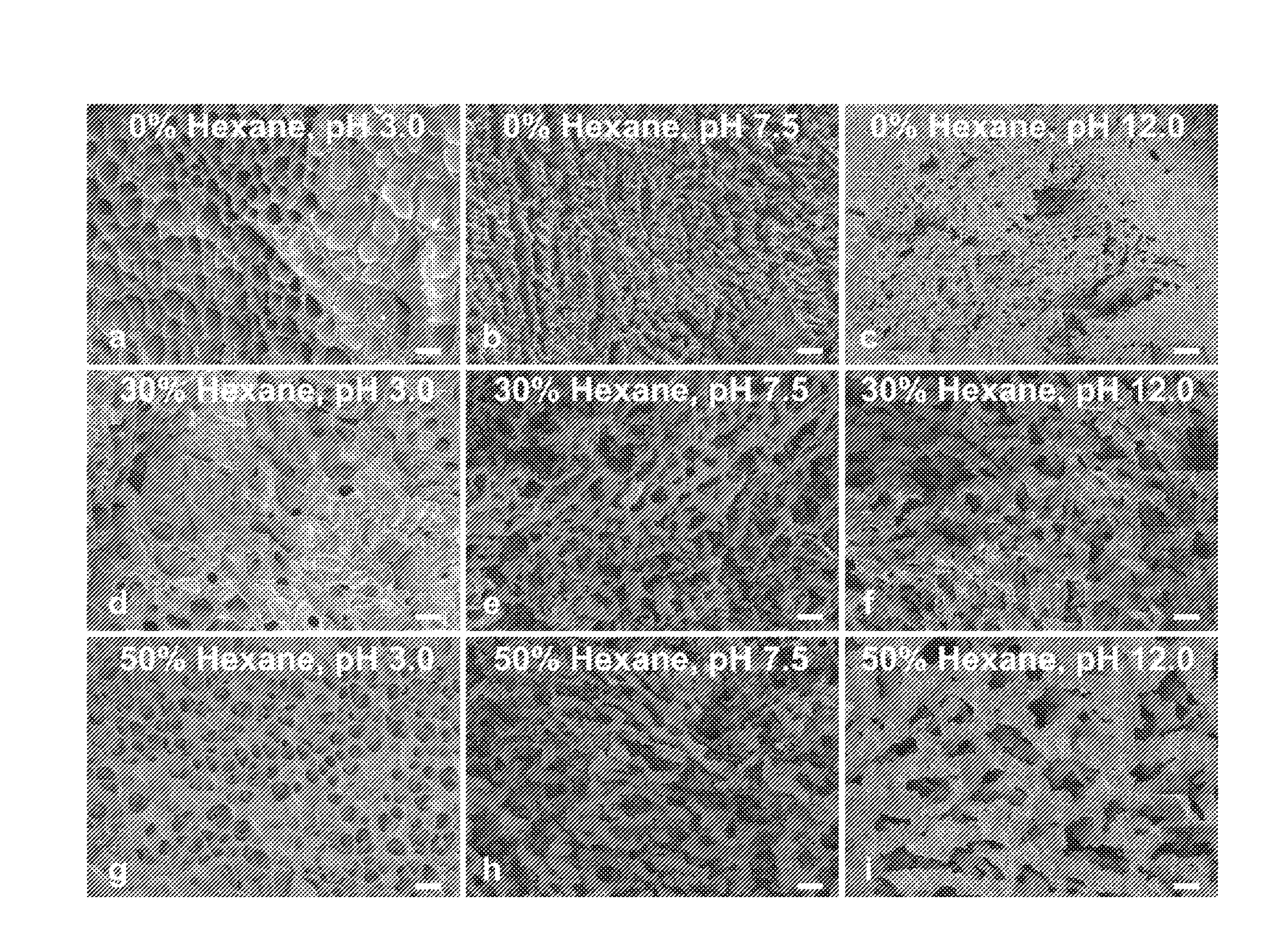
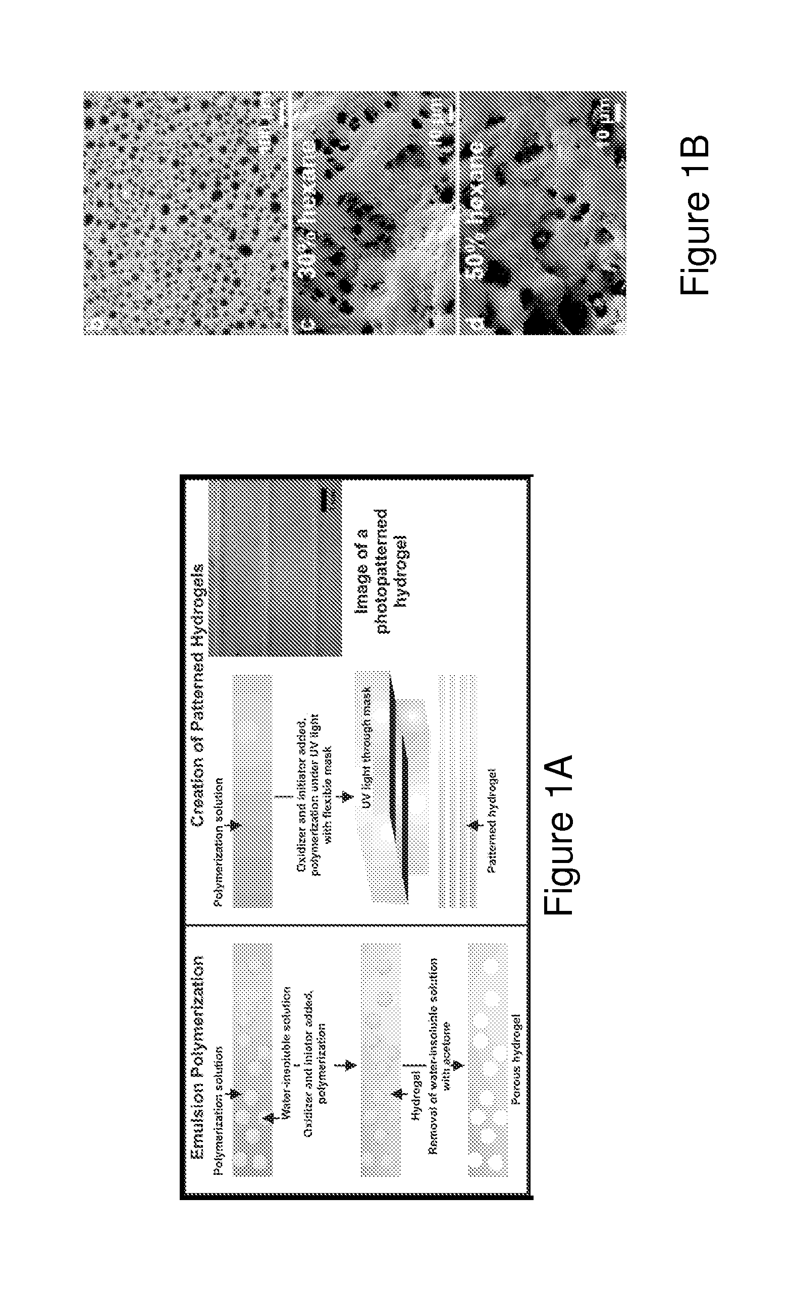
[0106]In order to optimize the electroactive hydrogel bending, an emulsion templating technique was employed to increase the hydrogel porosity (FIG. 1). The size of pores primarily depended on the volume fraction of the oil phase (hexane) utilized and the concentration of surfactant (Tween 20) added. Employing the emulsion templating method, a polydisperse distribution of pore sizes was generated, with the diameter of the smallest pores being ˜10 μm (FIG. 1c, d). By creating porous hydrogels using emulsion templating, bending angles of 70-90° were achieved with 2.5 V / cm electric field applied for 3 minutes (FIG. 4). This result represents a substantial improvement over previous studies where maximum bending angles of −30° to −40° (towards the cathode) were achieved when the electroactive hydrogels with the same dimensions were placed in 1.5 V / cm electric fields for 2 minutes (Moschou, E. A. et al. (2004) Chem. Mater. 16, 249...

example 2

Effects of a Spatiotemporal pH Gradient on Porous Electroactive Hydrogel Bending

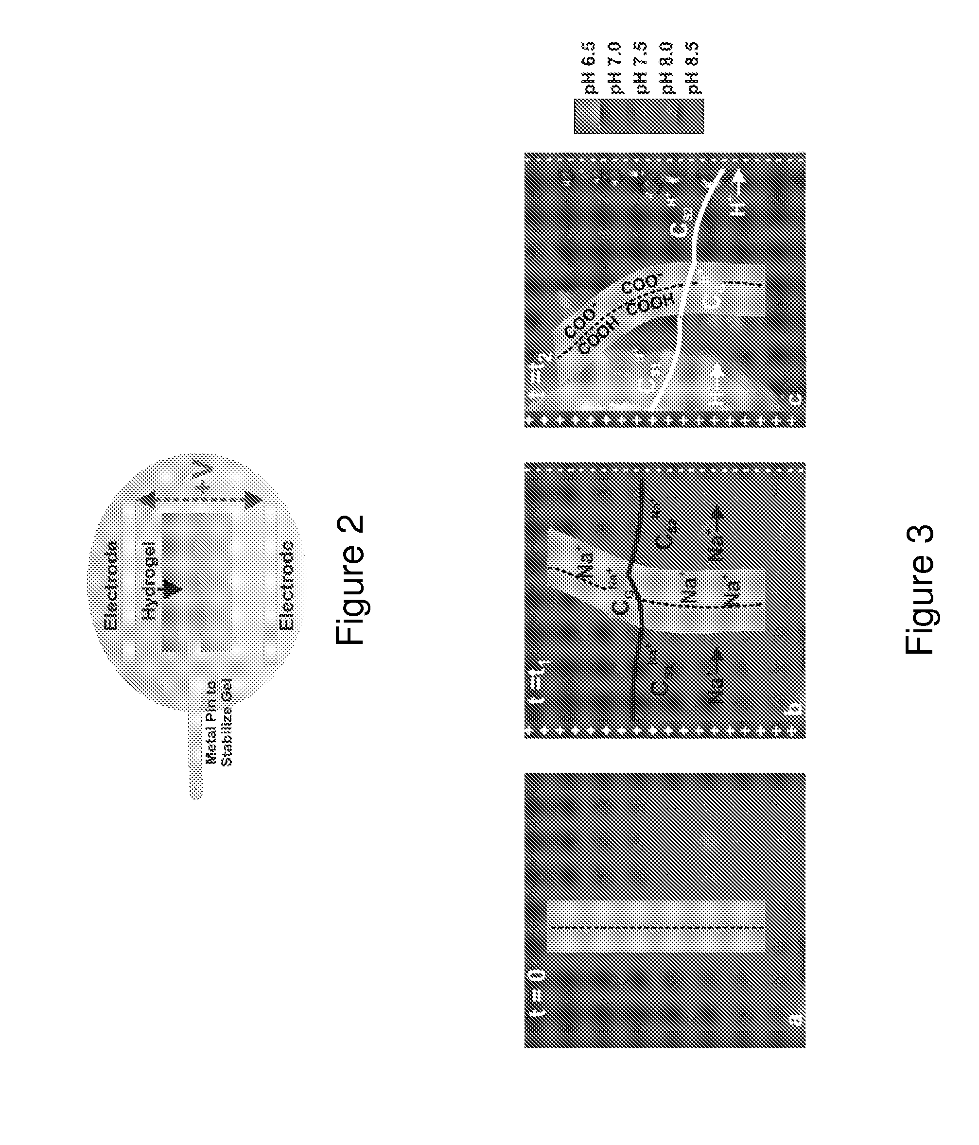
[0109]In this experiment, the effect of the spatiotemporal pH gradient on hydrogel bending, as well as the mechanisms underlying large bending of porous PAANa hydrogels were determined. The timescale and magnitude of these pH gradients can explain why larger deformation of PAANa hydrogels occurs in stronger electric fields. As larger electric fields are applied, a steeper pH gradient was created across the hydrogel (FIG. 5b,c), thus yielding a spatial gradient of COOH and COO− groups within the hydrogel. As more COOH groups were created within the hydrogel on the anode side relative to the cathode side, the polymer compressed on the COOH dominant (anode) side, generating a large bending angle.

[0110]The process of PAANa hydrogel bending is illustrated schematically in FIG. 3, where the extent of ionic gradients in the gel (CGNa+, CG+) depend on the fixed concentration of negative charges in the gel. Befor...

example 3

Effects of Porous Electroactive Hydrogel Density and Elasticity on Bending

[0112]Overall, both porous and non-porous hydrogels bend in a similar manner due to ion diffusion when no strong pH gradient is present. However, once a pH gradient is present, porous hydrogels produce larger bending angles than non-porous hydrogels since porous gels are less dense, such that they require less deswelling and compression on the anode side of the gel to produce a bending motion. For instance, a porous gel will have more void space and less polymer material within the cross-sectional area of the gel. Since the porous gels have less polymer material within the cross-sectional area of the gel, a smaller concentration of COOH groups must be generated across the cross-sectional area of the gel to cause the porous polymer to compress. It was observed that 50% thinner, non-porous hydrogels follow the same bending trajectory as porous hydrogels. Thin, non-porous hydrogels are able to bend to the same ex...


PUM

PropertyMeasurementUnit
angleaaaaaaaaaa
electric fieldaaaaaaaaaa
radiusaaaaaaaaaa

Abstract

The present invention provides porous electroactive hydrogels, the deformation angle of which is controlled by electroactuation, and methods for preparing and using such hydrogels.

Description

RELATED APPLICATIONS[0001]This application claims the benefit of and priority to U.S. Provisional Patent Application Ser. No. 61 / 194,079, filed on Sep. 24, 2008, and U.S. Provisional Application Ser. No. 61 / 200,609, filed on Dec. 2, 2008. The entire contents of each of the foregoing provisional applications are incorporated herein by reference.GOVERNMENT SUPPORT[0002]This invention was made with U.S. government support under grant nos. PHY-0117795 and DMR-0213805 awarded by the National Science Foundation and FA9550-05-1-0459 awarded by the U.S. Air Force Office of Scientific Research, Defense Advanced Research Projects Agency (DARPA) BioSenSE Program. The U.S. Government has certain rights in the invention.BACKGROUND OF THE INVENTION[0003]Hydrogels are hydrophilic polymer networks produced from reactions of one or more monomers or by association bonds between chains that can absorb from at least 20% to up to thousands of times their dry weight in water. Hydrogels may be chemically ...

Claims


Application Information

Patent Timeline
Patent Type & Authority Applications(United States)
IPC IPC(8): A61N1/30C12N5/071B01L3/00A61K47/30A61P9/00B01J39/20A61K35/12C12Q1/02
CPCA61F13/02A61F13/10A61F13/06A61L27/3633A61L27/3826A61L27/50A61L27/54A61L27/56A61P9/00
Inventor PARKER, KEVIN KITO'GRADY, MEGAN
Owner PRESIDENT & FELLOWS OF HARVARD COLLEGE
Learn More