
Electrode configuration of electrolysers to protect catalyst from oxidation

a technology of electrolyte and catalyst, which is applied in the field of electrolyte, can solve the problems of increasing cell voltage, increasing electrochemical losses, and current electrolyte technology is not mature enough for dynamic and intermittent operation, and achieves the effect of preventing the oxidation of anodic active catalyst materials

Inactive Publication Date: 2012-02-09
RE HYDROGEN
View PDF6 Cites 7 Cited by
  • Summary
  • Abstract
  • Description
  • Claims
  • Application Information

AI Technical Summary

Benefits of technology

[0012]In view of the above, the present invention provides an electrolyser comprising an anode and a cathode and having an electrode configuration with oxygen storage material deposited on the positive anode of the electrolyser in contact with anodic active catalyst material to prevent oxidation of the anodic active catalyst material by means of preferential oxidation of the oxygen storage material.

Problems solved by technology

However, the current electrolyser technology is not matured for dynamic and intermittent operation, which suffers from early failures compared to a desirable long life in smooth, steady state operation.
At high open circuit voltage during stand-by mode and shut-down mode the anodic active catalyst is gradually oxidised and thus the catalytic activity of the anode is decreased, leading to greater electrochemical losses and increased cell voltage which then increases the energy consumption of the electrolyser per unit volume of hydrogen production.
This in turn increases the energy consumption of electrolysers by more than 10% within a year.
The guaranteed quota of 2,500 cycles in conventional electrolysers is generally consumed in less than a year for on-off switching cycle of seven times per day which is unsuitable for renewable energy powered intermittent operation, because the electrolyser needs to be capable of an unlimited on-off switching cycle within its lifetime for renewable energy powered intermittent operation.
However, this approach is not feasible due to the limited operating range from 20-100% of alkaline electrolysers.
All these issues make protective current practically unfeasible or difficult to apply.
As a result current electrolysers are less compatible for renewable energy powered operation and as an example, the electrolyser used in a demonstration project of hydrogen and renewable integration at West Beacon Farm, Loughborough, Leicestershire, UK has been replaced due to stack failure within 2,000 on-off switching cycles and the replaced second stack has also suffered a similar degradation.

Method used


Image

  • Electrode configuration of electrolysers to protect catalyst from oxidation
  • Electrode configuration of electrolysers to protect catalyst from oxidation
  • Electrode configuration of electrolysers to protect catalyst from oxidation

Examples


example 1

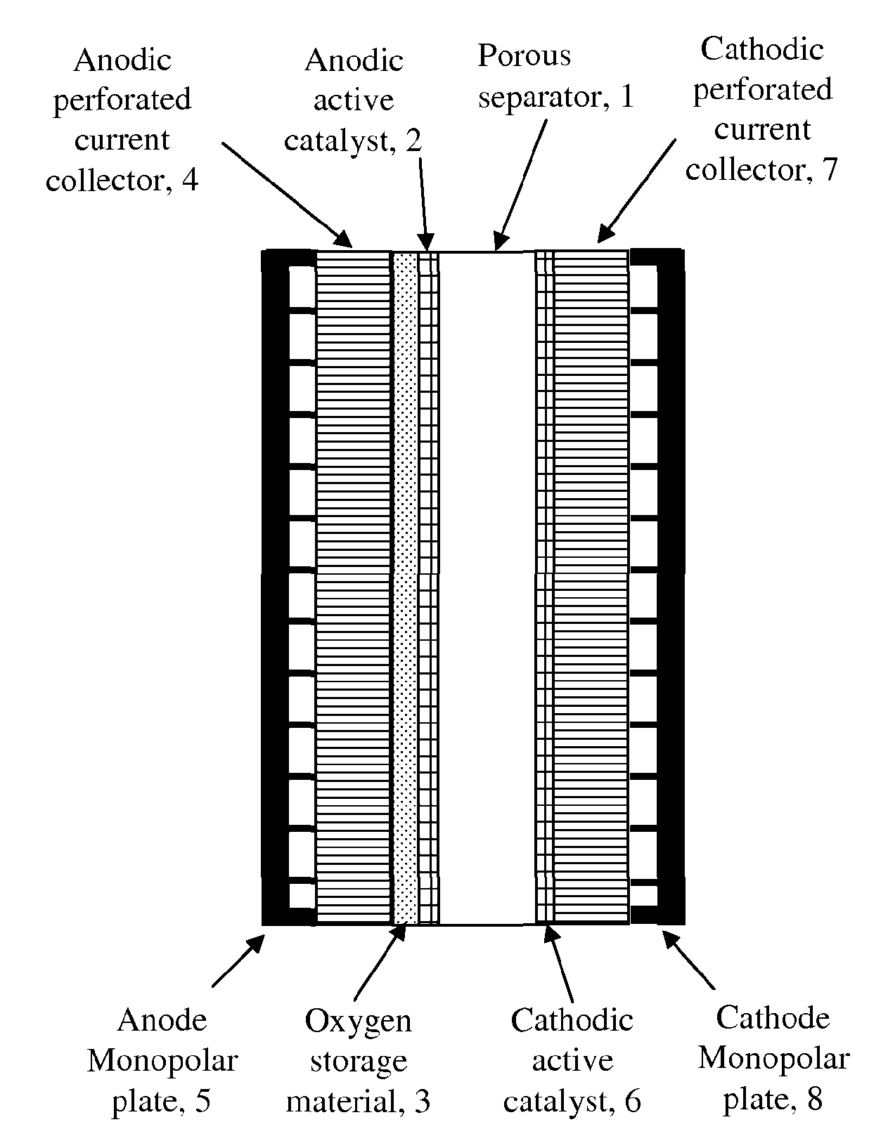
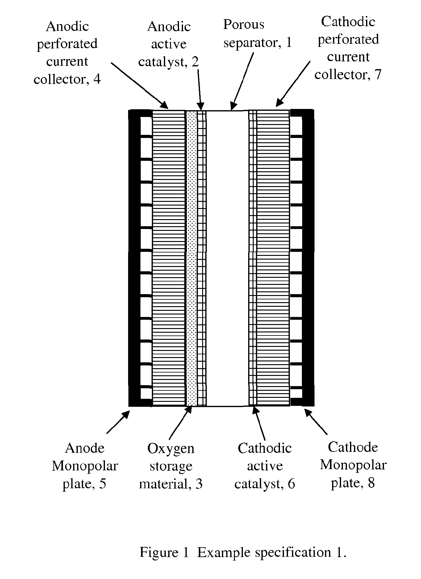
[0066]FIG. 1 shows the first example of one of the various electrode configurations according to an embodiment of the invention.

[0067]As shown in FIG. 1, oxygen storage material 3 is deposited onto an anodic perforated current collector 4 by various methods for example spraying, screen printing, hot pressing, sintering, thermal spraying, electroplating, electroforming, co-deposition by electroplating, electroless plating, dip coating, painting etc. The anodic active catalyst 2 is then deposited on top of the oxygen storage material 3 by various methods for example spraying, screen printing, hot pressing, sintering, thermal spraying, electroplating, electroforming, co-deposition by electroplating, electroless plating, dip coating, painting etc. The complete anode structure is then placed on one side of a porous separator 1.

[0068]An anode monopolar plate 5 is compressed to the back of the anodic perforated current collector 4 for supplying electricity and taking oxygen gas out of the ...

example 2

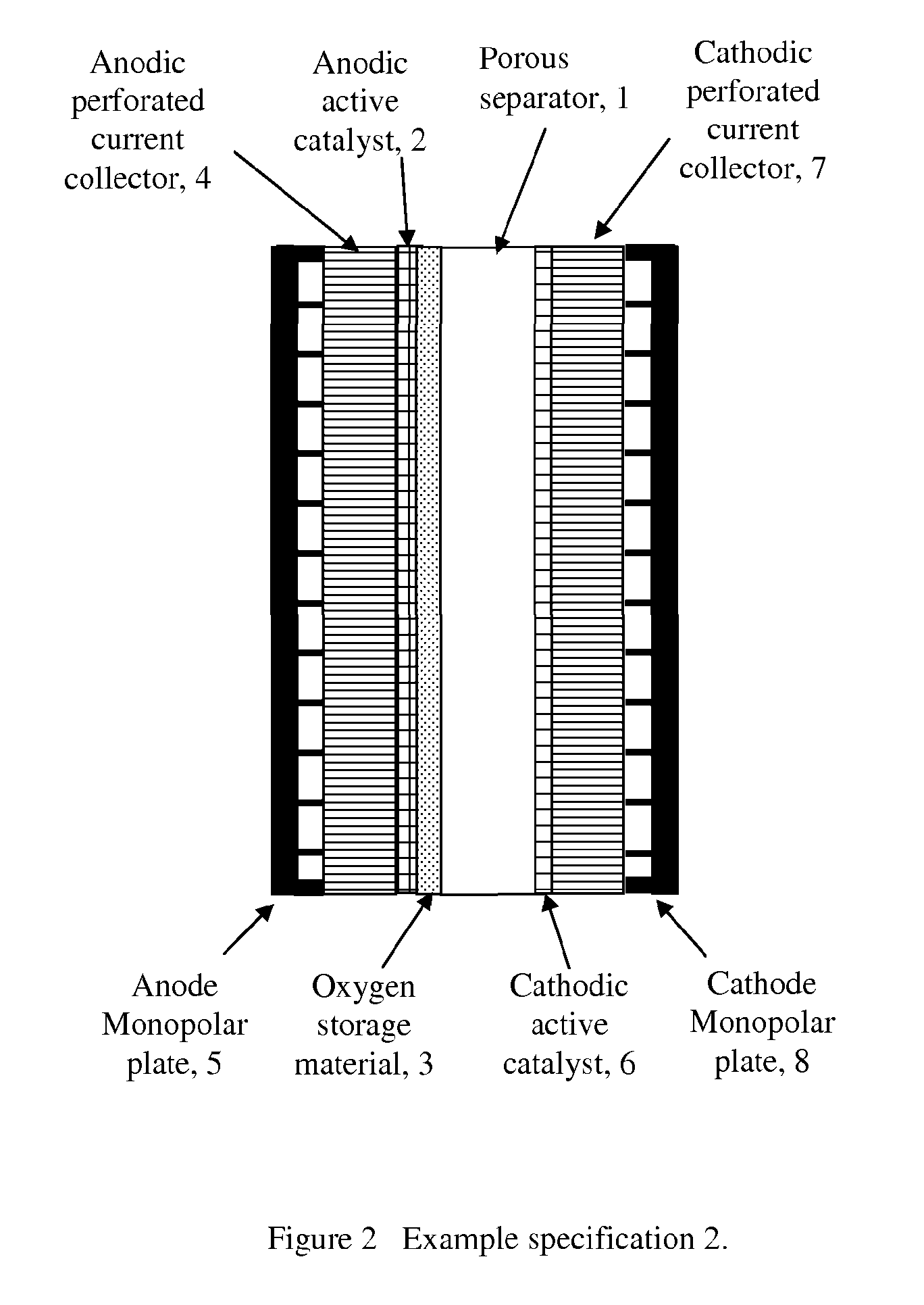
[0070]FIG. 2 shows the second example of one of the various electrode configurations according to an embodiment of the invention.

[0071]As shown in FIG. 2, an anodic active catalyst 2 is deposited onto an anodic perforated current collector 4 by various methods for example spraying, screen printing, hot pressing, sintering, thermal spraying, electroplating, electroforming, co-deposition by electroplating, electroless plating, dip coating, painting etc. Oxygen storage material 3 is then deposited on top of the anodic active catalyst 2 by various methods for example spraying, screen printing, hot pressing, sintering, thermal spraying, electroplating, electroforming, co-deposition by electroplating, electroless plating, dip coating, painting etc. The complete anode structure is then placed on one side of a porous separator 1.

[0072]An anode monopolar plate 5 is compressed to the back of the anodic perforated current collector 4 for supplying electricity and taking oxygen gas out of the c...

example 3

[0074]FIG. 3 shows the third example of one of the various electrode configurations described in accordance with an embodiment of the invention.

[0075]As shown in FIG. 3, an anodic active catalyst and oxygen storage material mixture 2 is deposited onto anodic perforated current collector 3 by various methods, for example spraying, screen printing, hot pressing, sintering, thermal spraying, electroplating, electroforming, co-deposition by electroplating, electroless plating, dip coating, painting etc. An anode monopolar plate 4 is compressed to the back of anodic perforated current collector 4 for supplying electricity and taking oxygen gas out of the cell.

[0076]A cathodic active catalyst 5 is deposited onto a cathodic perforated current collector 6 by various methods for example spraying, screen printing, hot pressing, sintering, thermal spraying, electroplating, electroforming, co-deposition by electroplating, electroless plating, dip coating, painting etc. A cathode monopolar plate...


PUM

PropertyMeasurementUnit
thicknessaaaaaaaaaa
open circuit voltageaaaaaaaaaa
porosityaaaaaaaaaa

Abstract

The invention relates to an electrode configuration of electrolysers using oxygen storage material to prevent oxidation of anodic active catalyst layer where oxygen storage material will be preferentially oxidised prior to anodic active catalyst. The inventions also relates to the use of hydrogen storage material with cathodic active catalyst to supply hydrogen to react with oxygen supplied from anodes when a reduction load is connected between the anode and cathode. One configuration utilises of individual layers containing oxygen and hydrogen storage materials, active catalyst layers, perforated current collectors, monopolar plates and a porous separator. A reduction load is used during operation of the electrolyser to convert metal oxides into pure metal by consuming oxygen from the electrolyser cell during stand by mode, shut down mode and intermittent operation, which will increase the durability of electrodes.

Description

FIELD OF INVENTION[0001]The present invention relates to an electrolyser and, in particular, to a renewable energy powered electrolyser for hydrogen production.BACKGROUND TO THE INVENTION[0002]Electrolysers powered by renewable energy sources produce hydrogen gas which can be used as transport fuel or backup electricity generation by fuel cells.[0003]However, the current electrolyser technology is not matured for dynamic and intermittent operation, which suffers from early failures compared to a desirable long life in smooth, steady state operation.[0004]Conventional alkaline electrolysers have a limited on-off switching cycle, for example only 2,500 cycles in conventional electrolysers for intermittent operation which are primarily used for steady state smooth operation in industrial applications.[0005]During stand-by mode and shut-down mode oxygen remains trapped inside the porous anodic catalyst layer and other parts of the electrolyser cell which then creates a high open circuit...

Claims


Application Information

Patent Timeline
Patent Type & Authority Applications(United States)
IPC IPC(8): C25B11/06C25B9/00C25B9/08C25B1/02C25B9/19
CPCC25B11/0442Y02E60/366C25B15/02Y02P20/133Y02E60/36C25B11/073C25B1/04C25B11/051
Inventor ROY, AMITAVA
Owner RE HYDROGEN
Features
  • Generate Ideas
  • Intellectual Property
  • Life Sciences
  • Materials
  • Tech Scout
  • Unparalleled Data Quality
  • Higher Quality Content
  • 60% Fewer Hallucinations
Learn More