
Optical waveguide-forming epoxy resin composition, optical waveguide-forming curable film, optical-transmitting flexible printed circuit, and electronic information device

a technology of epoxy resin and curable film, which is applied in the direction of circuit optical details, optical elements, instruments, etc., can solve the problems of not being able unable to utilize a mounting process that employs a reflow operation, and unable to meet the high-temperature reflow conditions of lead-free solder, etc., to achieve excellent flex resistance

Active Publication Date: 2012-02-09
PANASONIC CORP
View PDF3 Cites 23 Cited by
  • Summary
  • Abstract
  • Description
  • Claims
  • Application Information

AI Technical Summary

Benefits of technology

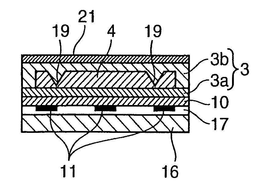
[0014]It is therefore an object of the present invention to provide an optical waveguide having excellent flex resistance which is to be formed on the surface of a flexible printed circuit.

Problems solved by technology

However, because acrylic resins have a low heat resistance, they are unable to withstand the high-temperature reflow conditions for lead-free solder.
Therefore, in cases where acrylic resin was used to form an optical waveguide on a substrate and an attempt was made to mount a photoelectric conversion element or the like at a light-receiving or light-emitting portion of the optical waveguide, it was found to be impossible to utilize a mounting process that employs a reflow operation.
Such a mounting process is very cumbersome and hardly conducive to mass production.
However, because the glass transition temperature (Tg) of epoxy resins is too high, such resins have basically a poor flexibility.
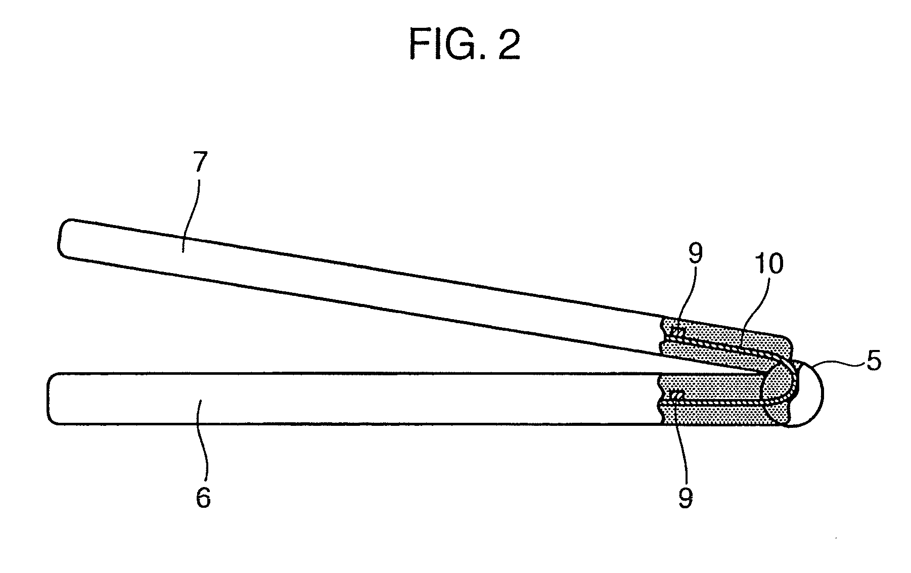
Even when polymer materials such as those disclosed in Patent Documents 1 to 3 are used, they lack sufficient flex to withstand use as an optical waveguide in a hinge.

Method used


Image

  • Optical waveguide-forming epoxy resin composition, optical waveguide-forming curable film, optical-transmitting flexible printed circuit, and electronic information device
  • Optical waveguide-forming epoxy resin composition, optical waveguide-forming curable film, optical-transmitting flexible printed circuit, and electronic information device
  • Optical waveguide-forming epoxy resin composition, optical waveguide-forming curable film, optical-transmitting flexible printed circuit, and electronic information device

Examples


examples

[0055]First, the starting materials used to prepare the epoxy resin compositions in the examples are listed below.

(A) Liquid Epoxy Compounds

[0056]Polyalkylene glycol diglycidyl ether: YL7410, available from Japan Epoxy Resins Co., Ltd.[0057]Polyethylene glycol diglycidyl ether: Epiol E-1000, available from NOF Corporation[0058]Epoxy compound of general formula (II): Epiclon EXA-4850-150, available from DIC Corporation[0059]Bisphenol A-type epoxy compound: Epiclon 850S, available from DIC Corporation[0060]Hydrogenated bisphenol A-type epoxy compound: YX8000, available from Japan Epoxy Resins Co., Ltd.[0061]Liquid ε-caprolactone-modified 3,4-epoxycyclohexenylmethyl-3′,4′-epoxycyclohexane carboxylate: Celloxide 2081, available from Daicel Chemical Industries, Ltd.

(B) Solid Epoxy Compounds

[0062]Bisphenol A-type epoxy compound: Epikote 1006FS, available from Japan Epoxy Resins Co., Ltd.[0063]Hydrogenated bisphenol A-type epoxy compound: YL7170, available from Japan Epoxy Resins Co., Ltd....


PUM

PropertyMeasurementUnit
pore sizeaaaaaaaaaa
thicknessesaaaaaaaaaa

Abstract

An optical waveguide of excellent flex resistance which is to be formed on the surface of a flexible printed circuit is obtained by using an epoxy resin composition includes (A) a liquid epoxy compound, (B) a solid epoxy compound, and (C) a cationic curing initiator, wherein as the liquid epoxy compound (A), (A1) a liquid epoxy compound represented by general formula (I) below is included:(where R1 and R2 are each independently a hydrogen atom or a methyl group; R3 to R6 are each independently a hydrogen atom, a methyl group, a chlorine atom or a bromine atom; R7 is an alkyleneoxy group or alkylene group of 1 to 15 carbons; p is 0 or 1; q is 1 to 25; r and s are 0 when p is 0, and are 1 when p is 1; and n is a positive integer which averages from 1 to 5).

Description

TECHNICAL FIELD[0001]The present invention relates to an epoxy resin composition for forming an optical waveguide to be disposed in, for example, the hinge of an electronic information device, a curable film obtained from the said epoxy resin composition, an optical-transmitting flexible printed circuit, and an electronic information device.BACKGROUND ART[0002]In electronic information devices, by using optical transmission to send and receive large amounts of information such as image data, efforts are being made to achieve high-speed processing while avoiding electromagnetic noise. A key elemental technology in such optical transmission are optical waveguide-based optical interconnections within the device for enabling signal transmission by converting electrical signals from an LSI chip or an integrated circuit, for example, into light. In internal optical interconnections, a 30 to 100 μm multimode waveguide is optimal to facilitate positioning between the optical input / output of...

Claims


Application Information

Patent Timeline
Patent Type & Authority Applications(United States)
IPC IPC(8): G02B6/12C08G59/30C08G59/24
CPCC08G59/226C08L63/00G02B6/138G02B6/43H05K1/0393H05K1/0274C08L2666/22C08G59/22C08J5/18H05K1/03
Inventor KONDOU, NAOYUKIYASHIRO, JUNKOHASHIMOTO, SHINJINAKASHIBA, TOHRU
Owner PANASONIC CORP
Learn More