Systems and Methods for Real-Time Tumor Tracking During Radiation Treatment Using Ultrasound Imaging

Active Publication Date: 2012-02-09
ACCURAY
View PDF12 Cites 141 Cited by
  • Summary
  • Abstract
  • Description
  • Claims
  • Application Information

AI Technical Summary

Benefits of technology

[0011]Embodiments of the present invention provide systems and methods for real-time tracking using ultrasound imaging of a structure, such as a tumor, during radiation treatment. Specifically, during patient set-up and/or throughout the radiation treatment procedure, an anatomy of interest, e.g. the treatment target, is ultrasonically imaged to track and compensate for motion in real-time. Because such imaging does not involve ionizing radiation, it may safely be performed continuously, or with a frequency that is substantially higher than a frequency with which images could be safely acquired using ionizing radiation. Additionally, ultrasound imaging is particularly well suited to imaging soft tissue, enabling the position and orientation of organs such as the prostate, kidneys, and the like to be monitored. Under some aspects of the present invention, x-ray or other conventional images are also obtained. As described in greater detail below, such images may be used to relate the reference frame of the ultrasound images to the previously obtained 3D treatment planning image. Under one aspect of the present invention, a system for tracking an anatomy of interest comprises an ultrasound probe configured to obtain ultrasound images of the ana

Problems solved by technology

Radiation beam delivery is, therefore, limited by the rotation range of the radiation source mounted on the gantry, the angular range of the gimbaled mechanism (if present), and by the number of degrees of freedom available on a patient positioning system.
In a typical gantry-based treatment system, a 3D cone beam CT set-up image is registered to a 3D planning image, a 3D to 3D registration problem.
Such motion can result in detrimental irradiation of otherwise healthy tissue, or over-irradiation of one part of the target volume and under-ra

Method used


Image

  • Systems and Methods for Real-Time Tumor Tracking During Radiation Treatment Using Ultrasound Imaging
  • Systems and Methods for Real-Time Tumor Tracking During Radiation Treatment Using Ultrasound Imaging
  • Systems and Methods for Real-Time Tumor Tracking During Radiation Treatment Using Ultrasound Imaging

Examples


example

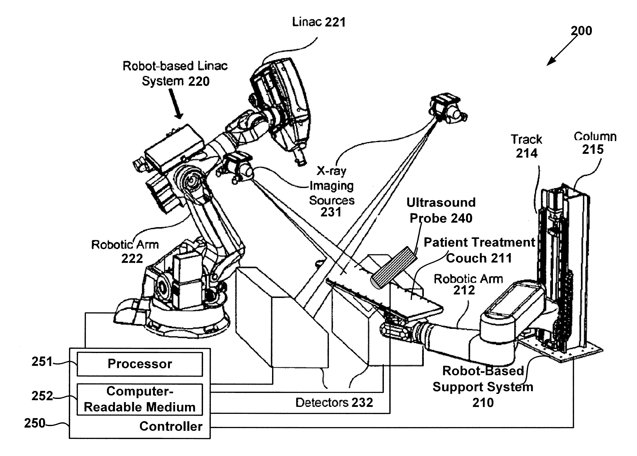
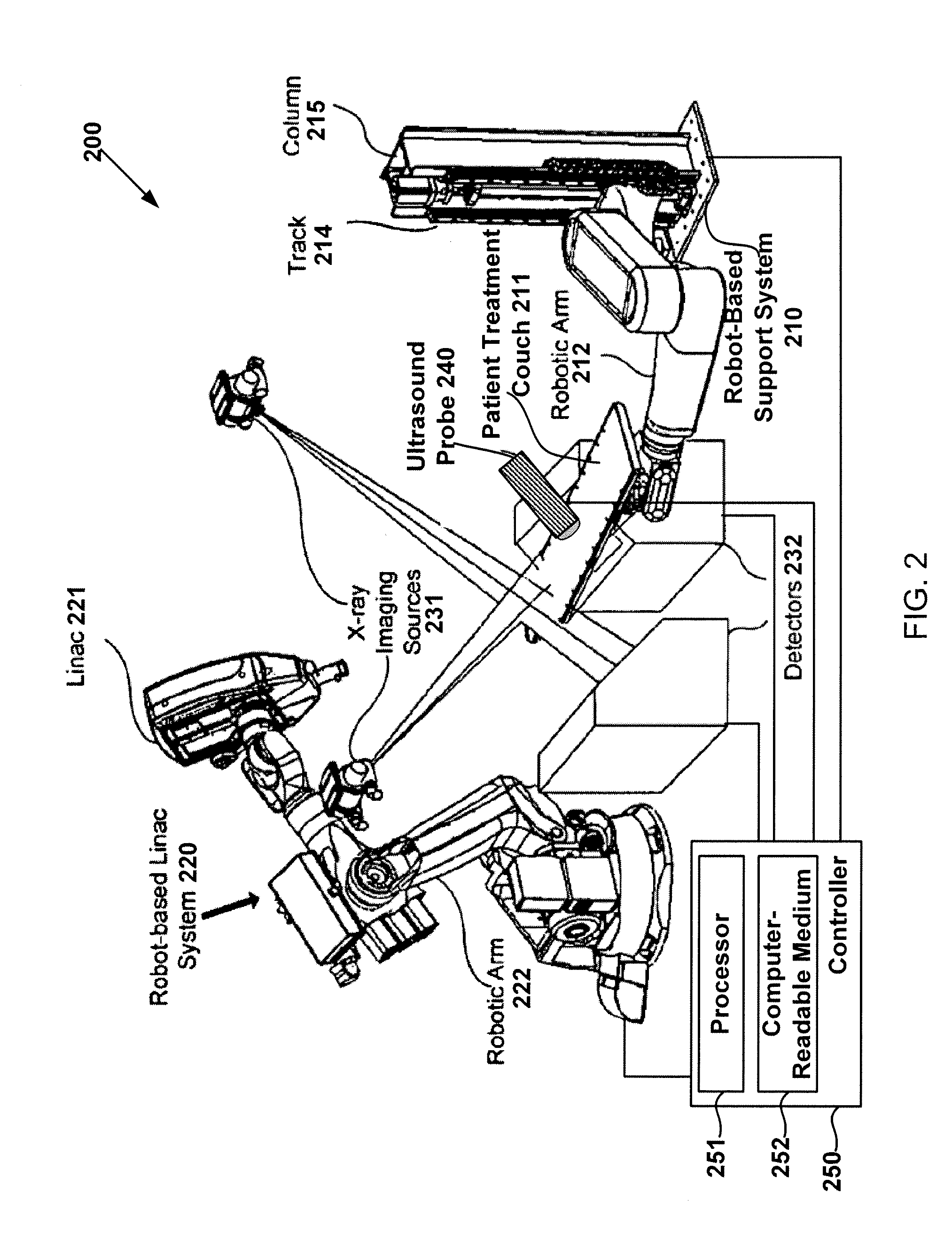
[0082]In one example, a radio-surgical procedure uses intrafractional ultrasound images to track movement of an anatomy of interest within a patient using system 200 of FIG. 2. The anatomy of interest may correspond to a target volume, e.g., a lesion, for irradiation by LINAC 221 or a structure within the patient that is fixed relative to the lesion. Prior to the procedure, a 3D planning image of the anatomy of interest patent is obtained using, e.g., a CT, MRI or other suitable imaging equipment. The 3D planning image is used by a physician to plan the procedure. After a treatment plan is developed, the planning image and treatment plan are accessible to controller 250 through the computer-readable medium 252.

[0083]The patient is placed on treatment couch 211 and aligned roughly with the reference frame adopted for the planning image, e.g., the geometric center of the lesion. Next, a transformation between the treatment room reference frame (the second reference frame) and the plan...


PUM


Abstract

Systems and methods for tracking a target volume, e.g., tumor, in real-time during radiation treatment are provided. Under one aspect, a system includes an ultrasound probe, an x-ray imager, a processor, and a computer-readable medium that stores a 3D image of the tumor in a first reference frame and instructions for causing the processor to: instruct the x-ray imager and ultrasound probe to substantially simultaneously obtain inherently registered x-ray and set-up ultrasound images of the tumor in a second reference frame; establish a transformation between the first and second reference frames by registering the 3D image and the x-ray image; instruct the ultrasound probe to obtain an intrafraction ultrasound image of the tumor; registering the intrafraction ultrasound image with the set-up ultrasound image; and track target volume motion based on the registered intrafraction ultrasound image.

Description

PRIORITY CLAIM[0001]The application claims priority to U.S. provisional application No. 61 / 371,596 filed Aug. 6, 2010 (docket no. 107501.2 / ARAY114Z), herein incorporated by reference in its entirety for all purposes.FIELD[0002]This application relates to systems and methods for locating and tracking an anatomy of interest during radiation treatment using ultrasound imaging.DISCUSSION OF RELATED ART[0003]External beam radiation therapy is one of the available non-invasive methods to treat a pathological anatomy (e.g., tumor, lesion, vascular malformation, nerve disorder, etc.). In one type of external beam radiation therapy, an external radiation source directs a sequence of x-ray beams at a target volume, e.g., a tumor, from multiple angles, with the patient positioned so the target volume is at the center of rotation (isocenter) of the beam. As the angle of the radiation source changes, every beam passes through the target volume, but passes through a different area of healthy tiss...

Claims


Application Information

Patent Timeline
IPC IPC(8): A61B8/13A61B5/055A61B6/03A61B8/00
CPCA61B6/022A61B6/0457A61B6/5247A61B8/08A61B8/4218A61B8/5238A61N5/1049A61N5/1067A61N5/107A61N5/1083A61N2005/1054A61N2005/1058A61N2005/1062A61B6/4417A61B6/4458A61B8/483A61B8/4245A61B2090/3995A61B90/39A61B5/055A61B8/085A61N5/1045A61N5/1077A61N2005/1055A61B8/4444A61B8/4416A61B8/5261A61B6/032A61B8/4263A61N5/1081A61N5/1039A61N2005/1061A61B6/0487
Inventor MAURER, JR., CALVIN R.WEST, JAYJORDAN, PETR
Owner ACCURAY
Why Eureka
Try Eureka