Apparatus and Method for Inspecting Laminated Structure

a laminated structure and apparatus technology, applied in the field of inspection of laminated structures, can solve the problems of large repair surface area that intrudes on other structures, limits the operator's ability to acquire data, and physical size too large to be incorporated, so as to reduce the above

Active Publication Date: 2012-02-09
THE BOEING CO
View PDF8 Cites 19 Cited by
  • Summary
  • Abstract
  • Description
  • Claims
  • Application Information

AI Technical Summary

Benefits of technology

[0008]It is an object of the present disclosure to eliminate or reduce the above described disadvantages. The following embodiments and aspects t

Problems solved by technology

Conventional pulse echo ultrasound is often reflected by the first delamination, and as a result it limits the operator from acquiring data on the delamination lying beneath it in a stratum of plies.
Another difficulty is that conventional transducers with sufficient energy and appropriately narrow beam spread, are physically too large to be incorporated in a transducer wedge that can be inserted in a small hole for inspection of the structure open to the hole.
A further disadvantage of existing solutions is that the maximum depth of the damage is unknown without repeated cycles of inspecting and sanding which results in removal of overlying material.
Since repairs often require a 30:1 taper on the sanded-out crater or “scarf”; small damage that is only a few plies deep can result in a large repair surface area that intrudes on other structures, and requires major disassembly.
Large repairs also may result in a large area exposed to heat when the repair plies ar

Method used


Image

  • Apparatus and Method for Inspecting Laminated Structure
  • Apparatus and Method for Inspecting Laminated Structure
  • Apparatus and Method for Inspecting Laminated Structure

Examples


third embodiment

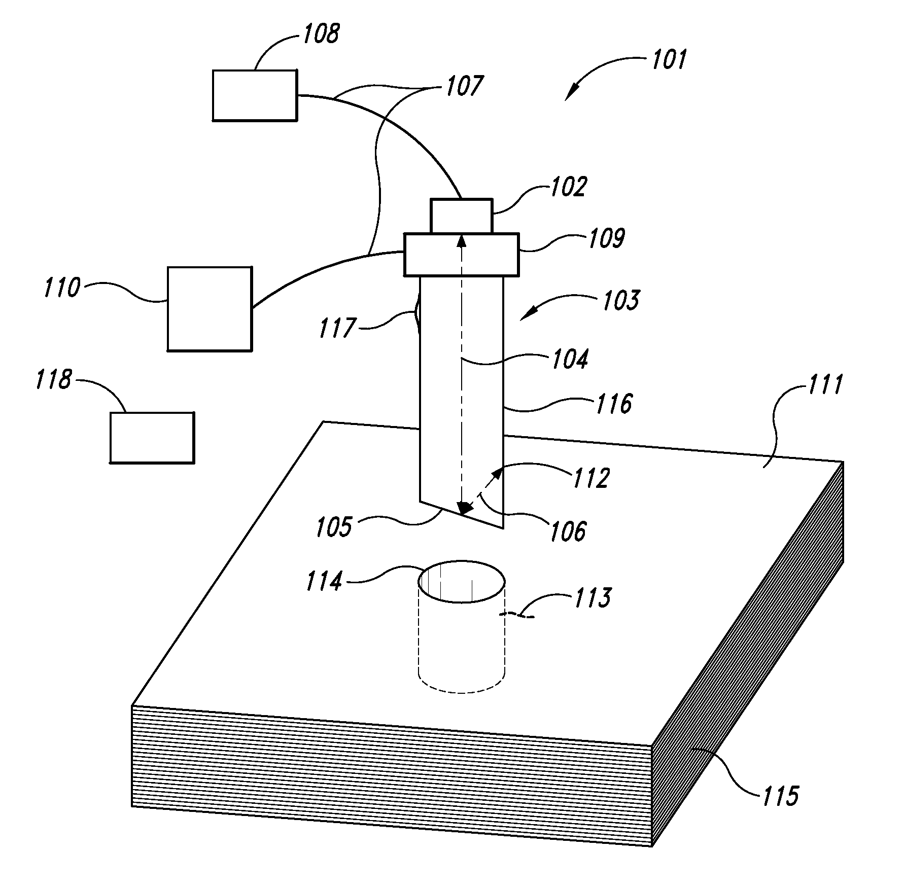
[0060]The third embodiment relates to a non-limiting, exemplary system for nondestructive inspection of a structure. At least one ultrasonic transducer assembly is proximate to the surface of the structure, and configured to transmit and receive ultrasonic energy to and from the structure. An ultrasonic pulser / receive is operatively coupled to the at least one ultrasonic longitudinal transducer. A computing system is operatively coupled to the ultrasonic pulser / receiver. The computing system includes a data acquisition component configured to acquire data from the ultrasonic pulser / receiver and a data analysis component configured to analyze the acquired data. The data analysis component may be further configured to analyze the acquired data for the condition of the structure. The system may also be configured to include a translation and rotation mechanism and controller for incrementing the transducer in various directions and circumferentially in a hole; and also accessories for ...

fourth embodiment

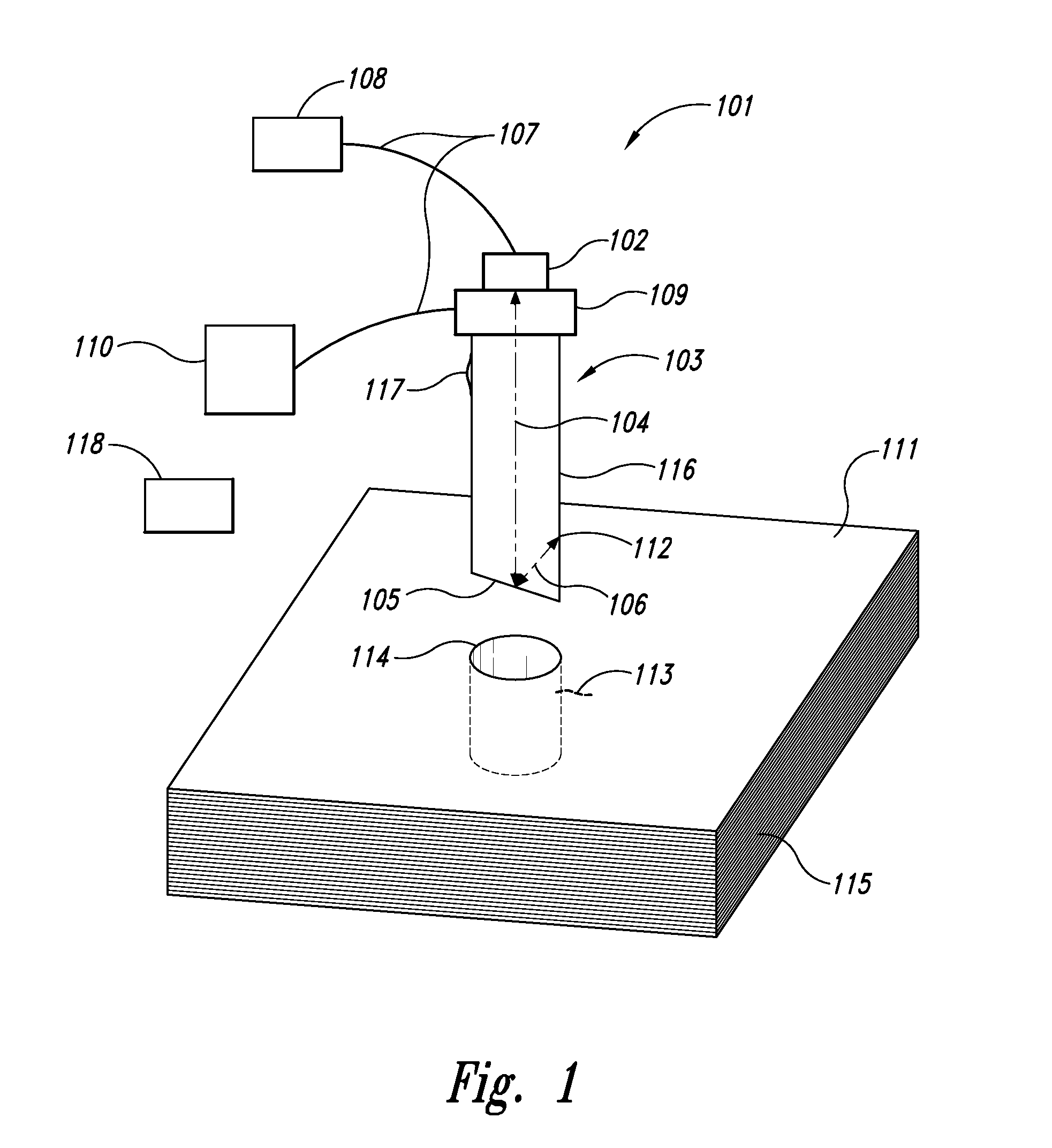
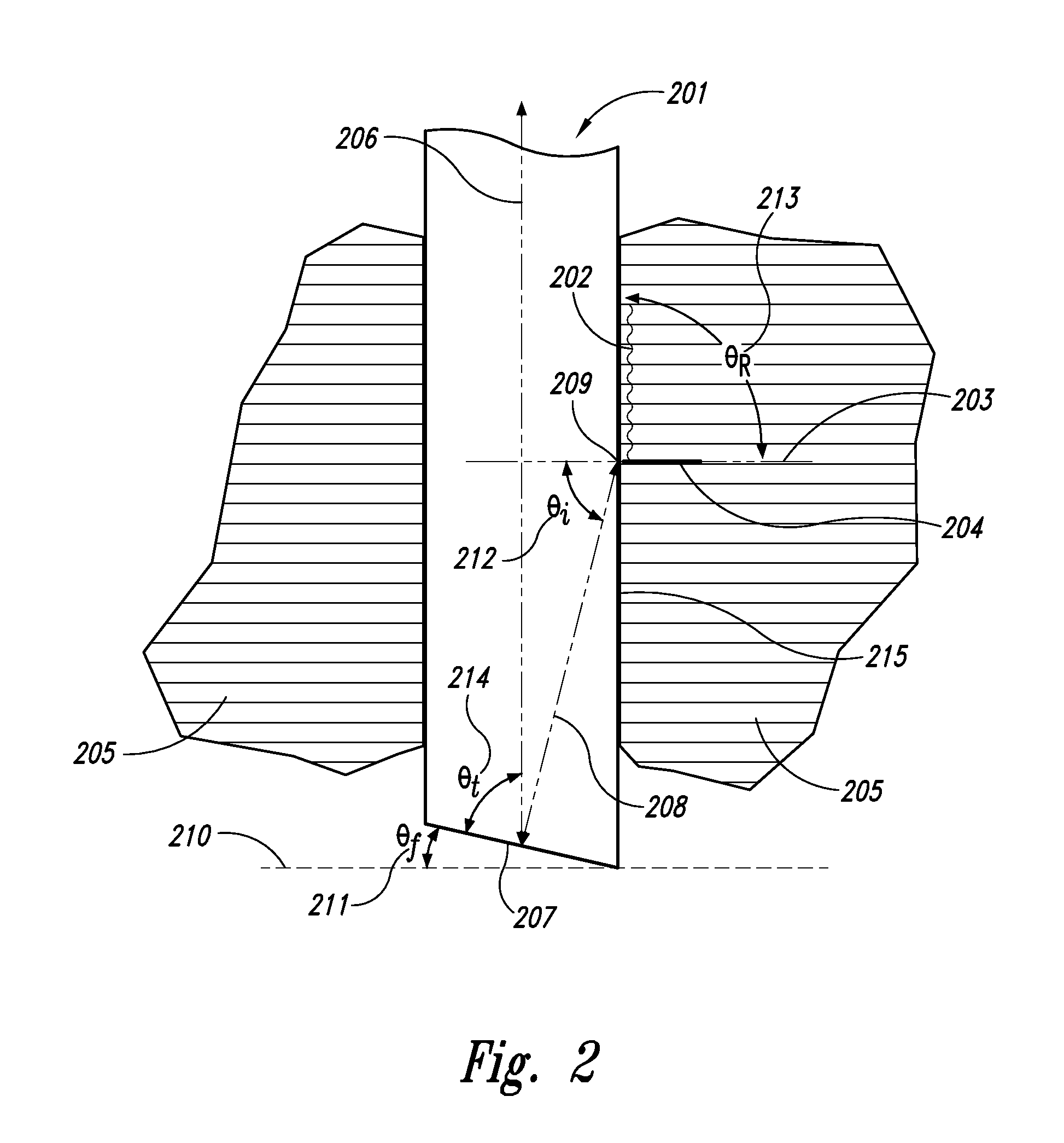
[0064]A fourth embodiment disclosed is a method of nondestructive inspection (NDI) of an airplane utilizing the disclosed apparatus and similar methods. The disclosed apparatus and method may be utilized to determine the condition of an airplane, for example, if a delamination discovered in an airplane wing skin also exists in the bonded airplane wing stiffener, NDI is a general term used for a variety of methods for evaluating structures, and can be required to be conducted by certified personnel in accordance with written procedures as defined in the enterprise non-destructive test specifications, and used for acceptance of parts, structures or components on airplanes or other vehicles. The ultrasonic transducer assembly can be advanced incrementally into the drilled hole and scanned circumferentially. Any signals occurring would be noted as depth in the hole and as circumferential position. The device is then incremented further and the process repeated to obtain a map of all dam...


PUM


Abstract

Disclosed is an apparatus, method and system for inspecting structures, and more particularly for evaluating the condition of a structure. The disclosed nondestructive inspection testing method and apparatus enables an operator to assess the condition of a structure, such as a composite laminate part and determining the location and depth of anomalies. The method includes generating a subsurface longitudinal ultrasonic wave signal at a high incidence angle into a structure being evaluated and collecting at least one of any front, back or side reflected wave data. The method may include processing the reflected wave data to determine the condition of the structure, including any anomalies that may have been detected and their location, size and shape.

Description

TECHNICAL FIELD[0001]The present disclosure relates generally to the inspection of structures such as composite fiber reinforced plastic (CFRP) used in aircraft or other structures, and more particularly to methods, apparatuses and systems for assessing the condition of a laminated structure.BACKGROUND[0002]Lightweight composite materials are being used more extensively in the aerospace industry for both commercial and military aircraft and other aerospace vehicles, as well as in other industries. The structures using these composite materials may be formed using multiple plies or layers of material that may be laminated together to form high strength structure. These structures may undergo further machining processes during manufacturing and assembly of vehicles (drilling, cutting, countersinking, shimming, fastener removal, etc.); as well as further processes related to flight and ground operations (maintenance, repair, retrofit, or overhaul); and damages from an impact or other c...

Claims


Application Information

Patent Timeline
IPC IPC(8): G01N29/04G01B5/28
CPCG01N29/043G01N29/07G01N2291/0235G01N2291/044G01N29/04G01N2291/0231G01N29/221G01N29/2462G01N29/2487
Inventor KOLLGAARD, JEFFREY R.TAPIA, WILLIAM J.
Owner THE BOEING CO
Why Eureka
Try Eureka