
Programmable diesel fuel injector

a diesel fuel injector and programmable technology, applied in the direction of fuel injection apparatus, electric control, charge feed system, etc., can solve the problems of limiting the speed of any injector using piezoelectric ceramic, and affecting the efficiency of fuel injectors

Inactive Publication Date: 2012-02-16
QUANTUM CONTROL WORKS L C
View PDF8 Cites 8 Cited by
  • Summary
  • Abstract
  • Description
  • Claims
  • Application Information

AI Technical Summary

Benefits of technology

[0055]An apparatus for injecting fuel into a combustion chamber of an internal combustion engine includes a solid magnetostrictive material with a favored direction of magnetostrictive response formed into a shape with ends that are substantially parallel to each other and substantially perpendicular to the favored direction of magnetostrictive response. A fuel control valve element is located coaxial to the favored direction of magnetoelastic response of the magnetostrictive material, the element opening inwardly. A solenoid coil is located concentric with the magnetostrictive material and coaxial to the favored direction of magnetoelastic response, the solenoid coil adapted to excite the magnetostrictive material into mechanical motion. An excitation signal is provided within the solenoid coil consisting of a signal, before a main current signal, sufficient to cause magnetic domain alignment but not rotation, and finally a magnetic return path circuit is provided in magnetic communication with the solid magnetostrictive material.

Problems solved by technology

However, admitting the combustible to maintain temperature results in net work since pressure remains higher than during the compression stroke.
Although, as described hereafter, appearing in the prior art are elements necessary for a very high speed rate shaping injector that take advantage of high pressure, none of the prior art discloses an injector which combines 1) use of high pressure with 2) continuously variable control over both stroke and speed 3) the durability to survive the heat and vibration present on a diesel engine cylinder head and 4) a simplified arrangement.
Piezoelectric ceramics have been known for decades yet the continuation of the art to rate shape using means that are primarily mechanical indicates the degree of difficulty that has been encountered in the employment of piezoelectric ceramics within fuel injectors.
Depending on the particular configuration, this limit may restrict the speed of any injector using piezoelectric ceramic.
The springs slow its speed and do not allow the stack to take advantage of the pressure available for preloading.
The low bulk modulus of liquid fuels requires much displacement to raise pressure significantly, meaning it will be difficult for such an actuator to provide meaningful pressure and flow.
Besides being complex to fabricate and not taking advantage of the high pressure available for better atomization, U.S. Pat. No. 6,079,636 will require big and bulky and therefore slow transducers.
Impact of a valve element causes a voltage spike to appear, which will cause the performance of the piezoelectric stack to degrade even faster than pointed out in U.S. Pat. No. 7,255,290, if it does not crack first.
Designing the injector to be closed with voltage applied means that removing voltage has the unfortunate consequence of allowing continuous injection in the event of a fault that disables that voltage.
The presence of bias magnets reduces magnetic permeability and therefore reduces electromechanical coupling, forcing input energy requirements to increase in compensation.
Bias magnets will add bulk and make handling difficult.
Second, the high compressive stress increases the variable Young's modulus of the terbium alloy.
Even though a spring that increases diameter would have the advantage of being shorter with less mass to accelerate, it may be very difficult to fit it onto a particular engine.
Friction and fretting wear on the edges of this type of spring would limit injector life.
The second kind of spring adds length and bulk which also add much more mass to be accelerated, limiting performance.
Besides mass, moving elements that are relatively long and thin will show a tendency to bend and vibrate and therefore would need to be guided, adding fabrication cost.
The spring itself will interact with the deflections and speed required, slowing the needle and introducing undesired motions to it.
Design and fabrication complexity is introduced by the need to compress the springs during assembly.

Method used


Image

  • Programmable diesel fuel injector
  • Programmable diesel fuel injector
  • Programmable diesel fuel injector

Examples


Embodiment Construction

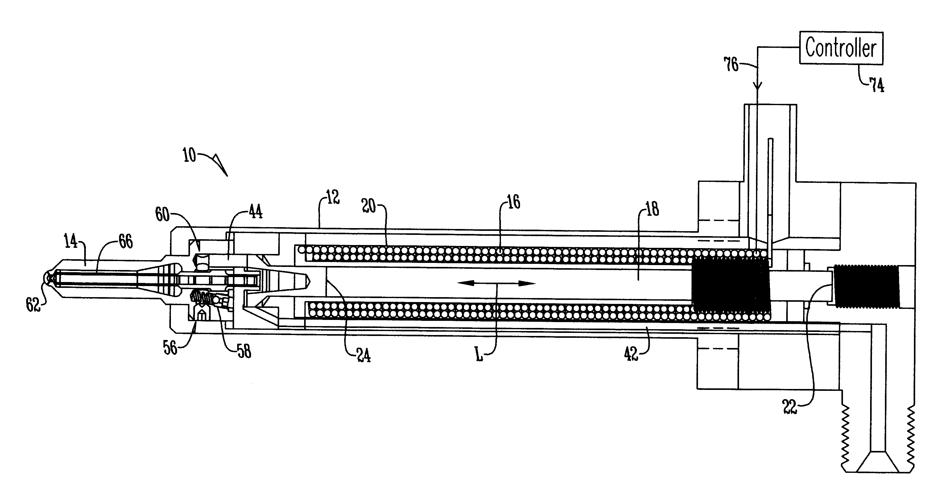
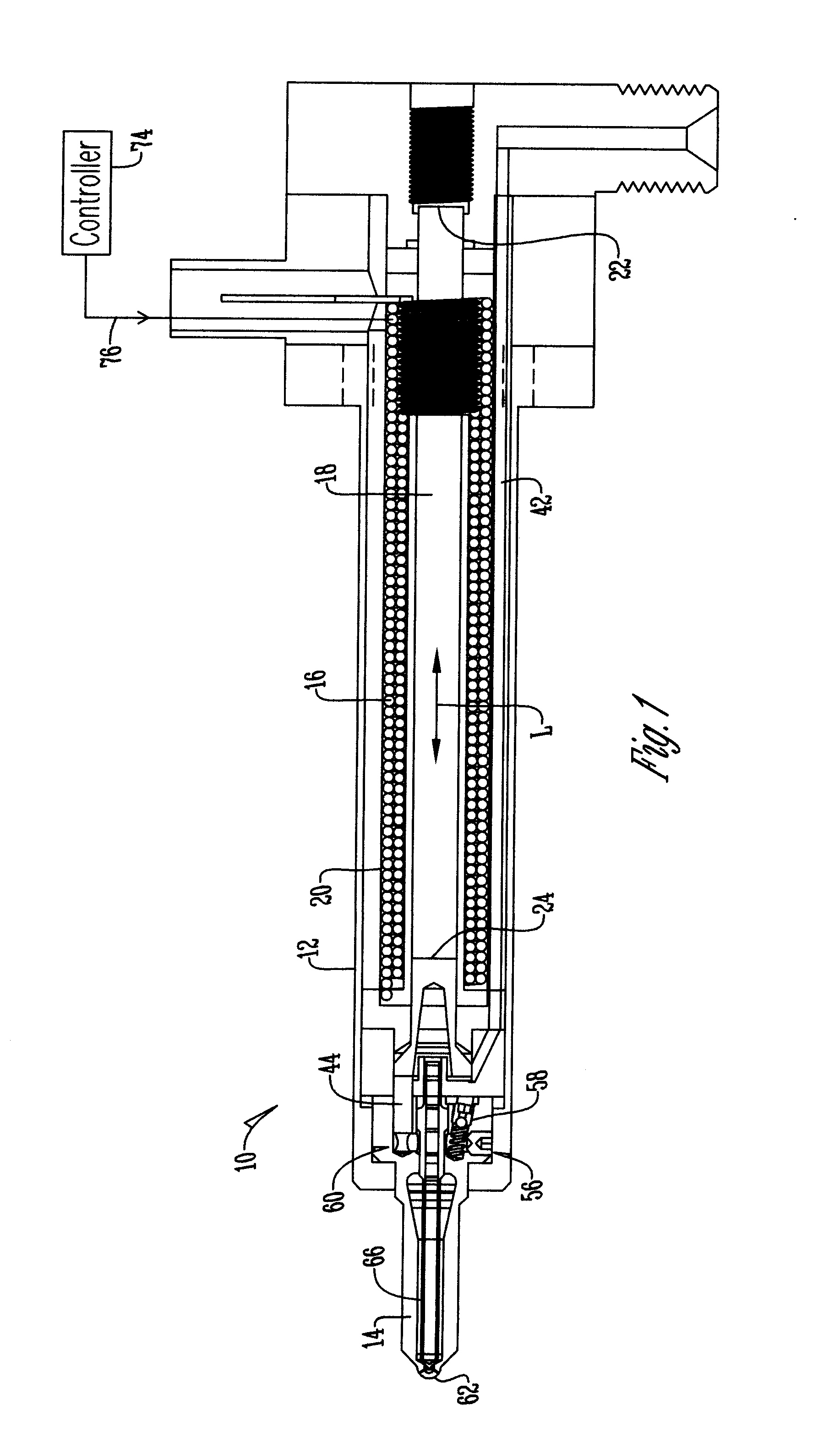
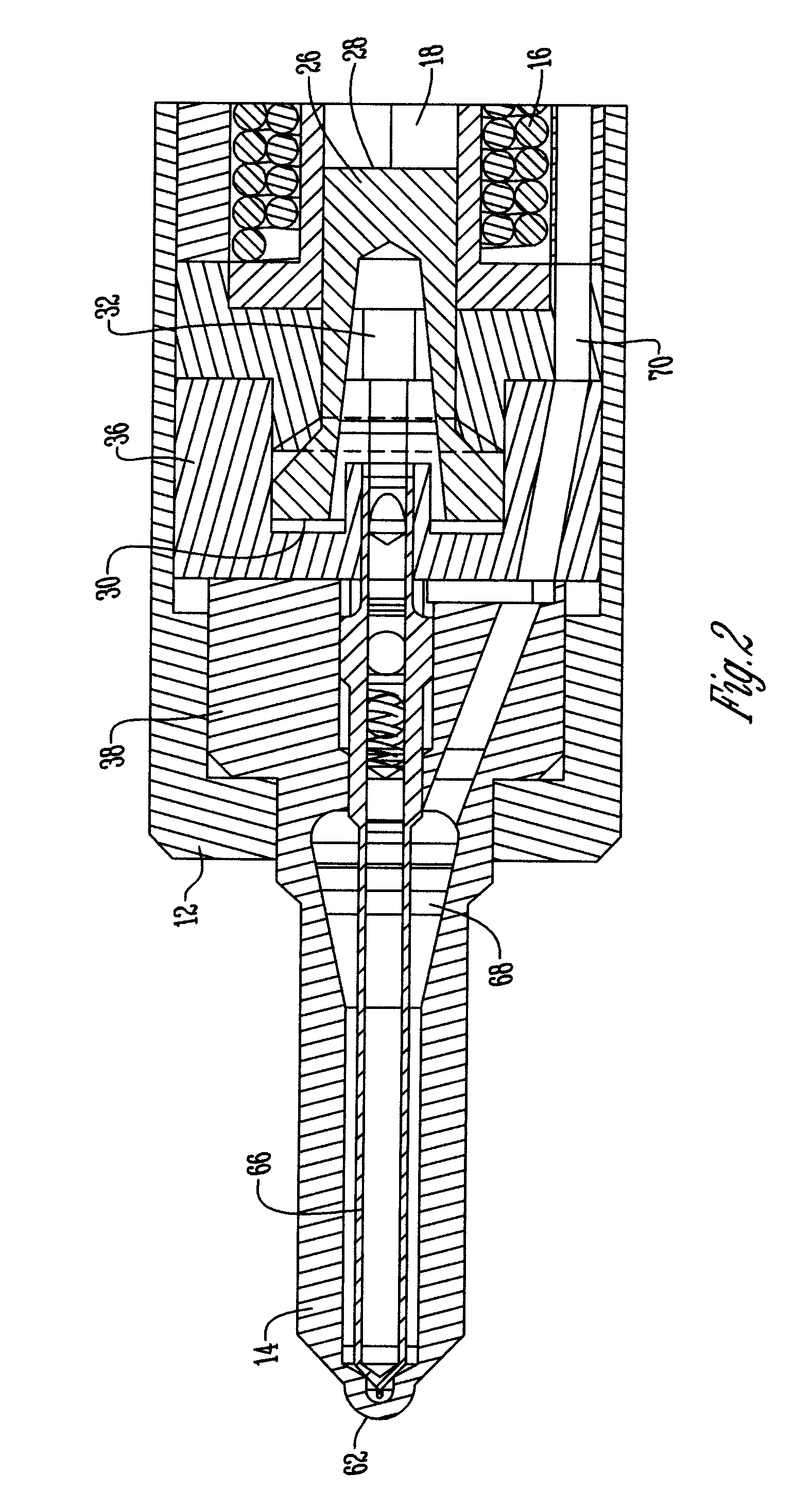
[0060]Referring to the figures, an apparatus for injecting fuel 10 (also referred to herein as a fuel injector) comprises a housing 12 including a nozzle 14 supported therein and protruding from one end of the housing 12. Also provided in the housing 12 is an electromechanical transducer including a helically wound solenoid coil 16 concentrically surrounding a magnetostrictive material 18 and a magnetic return path circuit 20 is concentric to the helically wound solenoid coil 16 in magnetic communication with the solid magnetostrictive material 18. The magnetostrictive material 18 is provided as a solid magnetostrictive material 18, which in a preferred embodiment, is comprised of terbium alloy, having a first end 22 and a second end 24 that are substantially parallel to each other and substantially perpendicular to a favored direction of magnetostrictive response, L. Furthermore, the solenoid coil 16, located concentric with the magnetostrictive material 18 and coaxial to the favor...


PUM


Abstract

An apparatus for injecting fuel into a combustion chamber of an internal combustion engine. The apparatus includes a solid magnetostrictive material with a favored direction of magnetostrictive response formed into a shape with ends that are substantially parallel to each other and substantially perpendicular to the favored direction of magnetostrictive response. A fuel control valve element is located coaxial to the favored direction of magnetoelastic response of the magnetostrictive material, the element opening inwardly. A solenoid coil is located concentric with the magnetostrictive material and coaxial to the favored direction of magnetoelastic response, the solenoid coil adapted to excite the magnetostrictive material into mechanical motion. An excitation signal is provided within the solenoid coil consisting of a signal, before a main current signal, sufficient to cause magnetic domain alignment but not rotation, and finally a magnetic return path circuit is provided in magnetic communication with the solid magnetostrictive material.

Description

TECHNICAL FIELD OF THE INVENTION[0001]The present invention relates generally to high pressure fuel injectors for internal combustion engines. More specifically, this invention is directed to a programmable diesel fuel injector with an internal electro-mechanical transducer with electrically selectable continuously variable control over stroke and speed that enables fuel injection rates of virtually any necessary shape, including multiple short pulses and / or gradual admission of the combustible fuel from the same injector, wherein the complexity required to form the rate shape is shifted from the mechanical portion of this simplified injector to electrical or electronic means.[0002]In Sadi Carnot's translated words: “The necessary condition of the maximum is, then, that in the bodies employed to realize the motive power of heat there should not occur any change of temperature which may not be due to a change of volume. Reciprocally, every time that this condition is fulfilled the ma...

Claims


Application Information

Patent Timeline
Patent Type & Authority Applications(United States)
IPC IPC(8): F02M51/00
CPCF02D41/20F02D2041/2027F02D2041/2044F02M51/0603
Inventor BRIGHT, CHARLES B.
Owner QUANTUM CONTROL WORKS L C
Learn More