Electromagnetic interference shield

a technology of electromagnetic interference and shielding, applied in the direction of optical radiation measurement, photometry using electric radiation detectors, instruments, etc., can solve the problems of indiscrete electrical current in conductive materials, system performance is still compromised, and the electrical signaling and control circuit may be disrupted, so as to increase the efficiency of emi shielding and block radio waves , the effect of significant transparency

Inactive Publication Date: 2012-02-16
FLIR SYST INC
View PDF7 Cites 68 Cited by
  • Summary
  • Abstract
  • Description
  • Claims
  • Application Information

AI Technical Summary

Benefits of technology

[0004]The present teachings disclose an improved EMI shielded detection system, including apparatus and methods of use. The disclosed system may include features configured to increase blockage of radio wave and/or microwave radiation while retaining significant transparency at visible and/or infrared wavelengths, thus increasing EMI shielding efficiency. This may be accomplished

Problems solved by technology

However, electro-optical signaling and control circuits may be disrupted by electromagnetic interference (EMI), such as microwave radiation or radio wave radiation, which can induce indiscrete el

Method used


Image

  • Electromagnetic interference shield
  • Electromagnetic interference shield
  • Electromagnetic interference shield

Examples


examples

[0055]This section describes exemplary electromagnetic interference shields, in accordance with aspects of the present disclosure, presented without limitation as a series of numbered paragraphs.

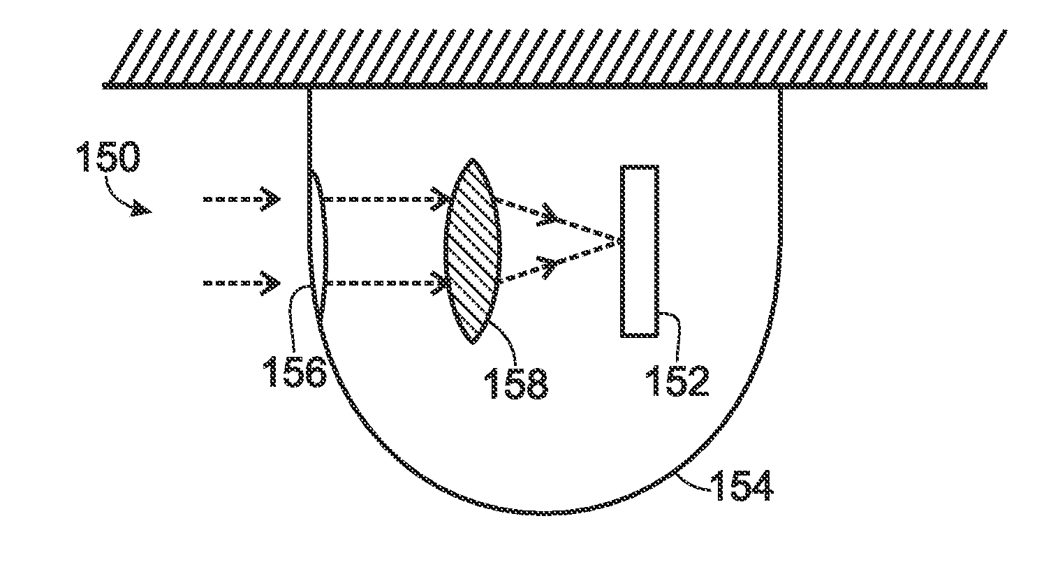
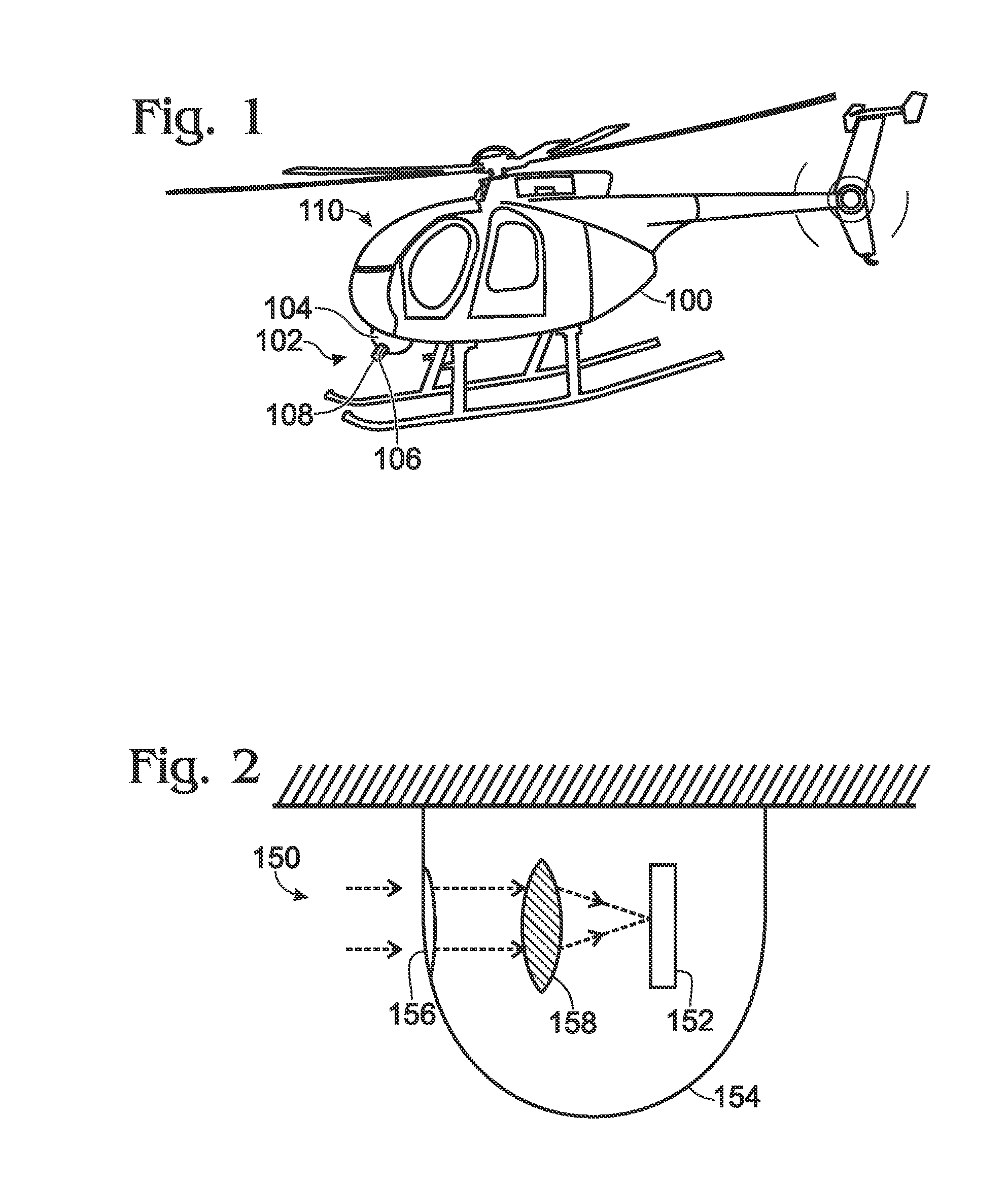
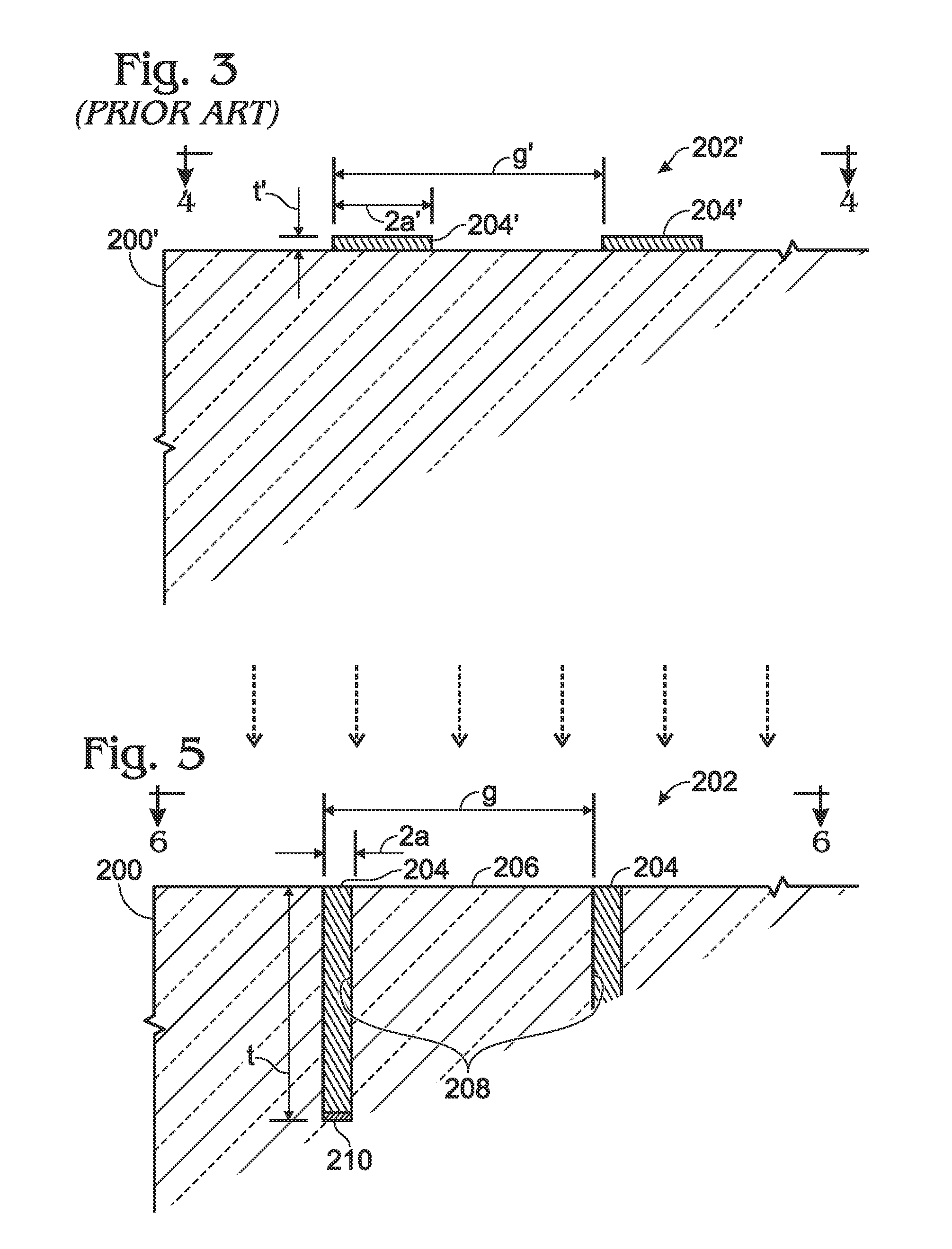
[0056]1. A shielded detection system, comprising (A) an infrared radiation detector configured to detect infrared radiation; (B) a housing at least substantially surrounding the detector and including a window substantially transparent to infrared radiation; and (C) an optical relay structure operatively disposed between the window and the detector and configured to direct infrared radiation transmitted through the window onto the infrared radiation detector; wherein the window includes an electrically conductive mesh configured to allow substantial passage of infrared radiation into the housing while preventing substantial passage of microwave radiation; wherein the mesh is formed of strands each having an oblong cross-section oriented with a longer dimension of the cross-section aligned su...


PUM

PropertyMeasurementUnit
Fractionaaaaaaaaaa
Threshold limitaaaaaaaaaa
Electrical conductivityaaaaaaaaaa

Abstract

An improved EMI shielded detection system. The disclosed system may include features configured to increase radio wave and microwave absorbance while retaining significant transparency at visible and/or infrared wavelengths, thus increasing EMI shielding efficiency. This may be accomplished through the use of a conductive mesh having appropriately chosen dimensions and spacing, and embedded in a transparent medium. To minimize the impact of the mesh on the effective aperture of the medium, the strands of the mesh may be made relatively narrow, and to provide sufficient shielding despite the narrow strand width, the mesh may be embedded relatively deeply in the medium.

Description

INTRODUCTION[0001]Imaging systems may include electro-optical photodetectors that generate discrete electronic signals in response to incident photons, such as visible light or non-visible ultraviolet (UV) or infrared (IR) radiation. For example, digital cameras may focus an optical image onto a focal plane array that generates electronic signals representative of the image, which then may be processed, displayed, and / or recorded. Digital imaging systems may provide substantial utility advantages over other (e.g., photochemical) systems, such as sensitivity, response range, temporal density, dynamic filtering, and quantitative analysis. However, electro-optical signaling and control circuits may be disrupted by electromagnetic interference (EMI), such as microwave radiation or radio wave radiation, which can induce indiscrete electrical currents in conductive materials. Some electro-optical systems, such as certain surveillance, satellite, and weapon systems, may be required to imag...

Claims


Application Information

Patent Timeline
IPC IPC(8): G01J5/00H05K13/00G01J1/04
CPCG01J2001/0276H01Q1/425H01Q17/005Y10T29/49002
Inventor STRICKLAND, WILLIAM B.
Owner FLIR SYST INC
Why Eureka
Try Eureka