Passively mode-locked picosecond laser device

a laser device and mode-locked technology, applied in the direction of laser details, optical resonator shape and construction, electrical equipment, etc., can solve the problems of low stability performance of mode-locked laser devices, short life time, and difficulty in large-scale production of mode-locked picosecond laser devices. , to achieve the effect of increasing the optical path, reducing the length and volume of the cavity, and reducing the repetition frequency

Inactive Publication Date: 2012-02-16
BEIJING GK LASER TECH
View PDF8 Cites 14 Cited by
  • Summary
  • Abstract
  • Description
  • Claims
  • Application Information

AI Technical Summary

Benefits of technology

[0020]Compared with the existing technologies, the present invention innovatively uses a equivalent confocal stable cavity, increasing the optical path, reducing the repetition frequency, and greatly decreasing the cavity length and volume.
[0021]Also, the laser crystal is placed in the gap of the laser cavity or embedded in the end of the laser cavity, resulting in the structure more compact.

Problems solved by technology

Also, the dye, being of highly toxic, would be diluted after some time, so needs to be replaced, therefore the life time is short which is not facilitated for industrialization and human health.
Because the technology of wave-guide is developed prematurely and the yield is very low, it is difficult to produce mode-locked picosecond laser device in large scale, and such active mode-locked has low stability performance.
To sum up, the existing technologies are lack of a low-repetition-frequency passive mode-locked picosecond laser with compact structure and stable performance.

Method used


Image

  • Passively mode-locked picosecond laser device
  • Passively mode-locked picosecond laser device
  • Passively mode-locked picosecond laser device

Examples


embodiment 1

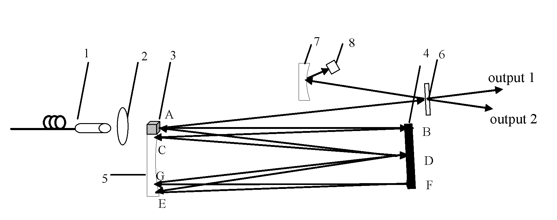
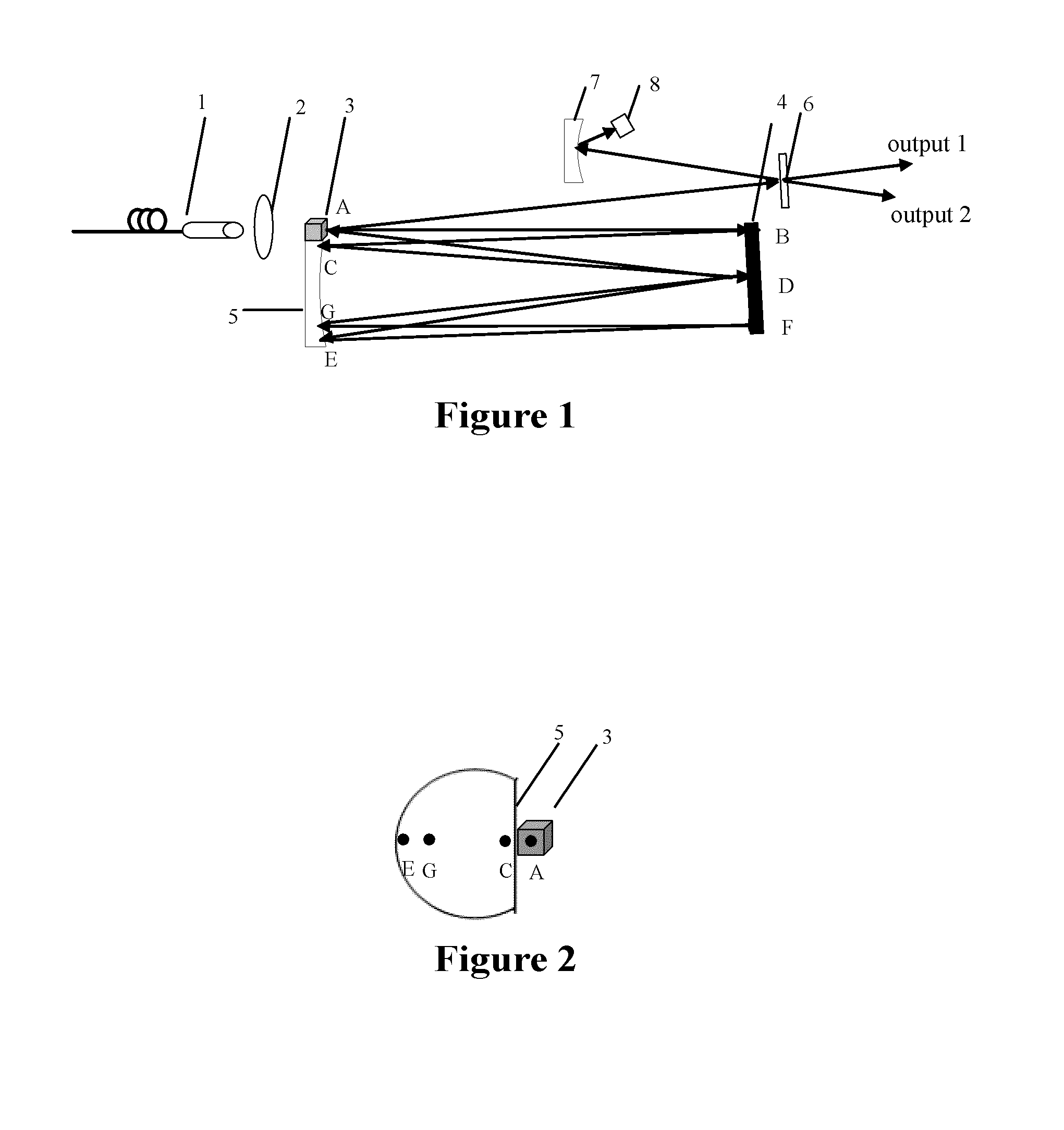
[0028]As shown in FIG. 1, the passive mode-locked picosecond laser device according to Embodiment 1 of the present invention comprises: a LD pump source 1, a focusing lens 2, a laser crystal 3, a plane reflective mirror 4, a first plano-concave mirror 5 (Φ=20 mm), a plane output mirror 6, a second plano-concave mirror 7 (Φ=10 mm) and a SESAM (semiconductor saturable absorber) 8. The LD pump source 1 is placed at the side of the incidence end of the laser crystal 3 for pumping the laser crystal. The focusing mirror 2 is placed between the pump source 1 and the laser crystal 3 for converging the pumping light coming from the pump source 1 into the laser crystal 3, increasing the utilization rate of the pumping light. The plane reflective mirror 4 is placed opposite to the first plano-concave mirror 5 and located at the position of the focal radius of the first plano-concave mirror 5, both of which constitute together a laser cavity (an equivalent confocal cavity). The normal direction...

embodiment 2

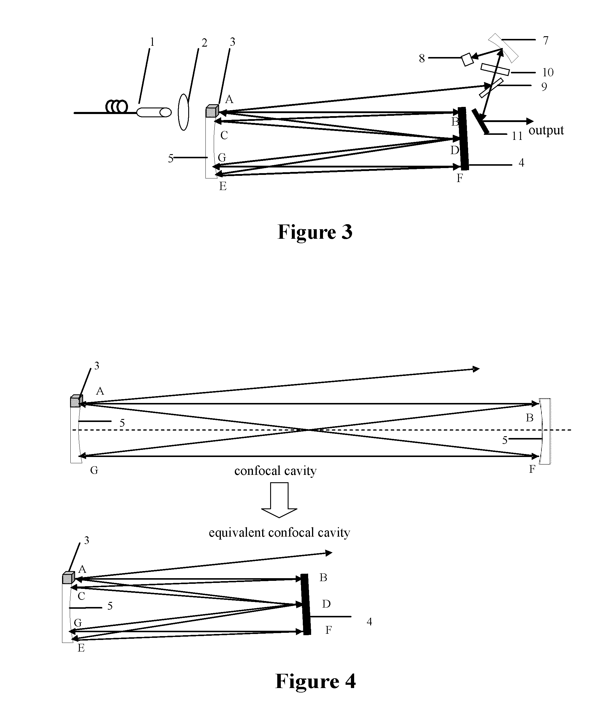
[0034]As shown in FIG. 3, the passive mode-locked picosecond laser device according to Embodiment 2 of the present invention comprises a LD pump source 1, a focusing lens 2, a laser crystal 3, a plane mirror 4, a first plano-concave mirror 5, a second plano-concave mirror 7, a SESAM 8, a polarizer 9, a ¼ wave plate 10, and a 45° reflector 11. In this embodiment, the LD pump source 1, the focusing mirror 2, the laser crystal 3, the plane mirror 4 and the first plano-concave mirror 5 are arranged as same as Embodiment 1.

[0035]The second plano-concave mirror 7, the SESAM 8, the polarizer 9, the ¼ wave plate 10 and the 45° reflector 11 constitute the mode-locked output structure which is placed on a position capable of being calibrated through laser. The calibration process is as follows: a laser beam is directed parallel to the normal of the first plano-concave mirror 5 from the center of the laser crystal 3 toward the plane reflective mirror 4. The polarizer 9 is placed on the outgoin...


PUM


Abstract

A passively mode-locked picosecond laser device comprising a pump source, a laser crystal, a laser cavity, a mode-locked output structure is provided. In the device, the pump source is placed at the side of the incident end surface of the laser crystal; the laser cavity includes a plane reflective mirror and a first plano-concave mirror, the reflective mirror is placed opposite to the concave surface of the plano-concave mirror and located on the position of the focal radius of the plano-concave mirror. The normal direction of the reflective mirror and the axis of the plano-concave mirror form a small angle therebetween; the laser generated from the laser crystal oscillates in the laser cavity, and output through the mode-locked output structure. The device uses a stable cavity design of the equivalent confocal cavity, which can increase the optical path, reduce the repetition frequency, and significantly reduce the cavity length and volume.

Description

FIELD OF THE INVENTION[0001]The present invention relates to an ultra-short pulse laser device, and particularly to a passive mode-locked picosecond laser device.BACKGROUND OF THE INVENTION[0002]With the rapid development of laser technology and the increasing application demand thereof, the tendency of laser field is to realize the high-power, high beam quality, high efficiency, high stability and long life of a laser device which is in small size, compact structure, stable performance, and all solid state. In a variety of technical fields and industries, the demand for ultra short pulse laser is increasingly higher, especially for the picosecond laser, which has more application prospect than a femtosecond laser (for example, the fields of the national defense, industrial, medical, biological, and other areas). Therefore, a current important research task is to develop a high-quality, high efficiency, high stability picosecond laser.[0003]According to one existing picosecond laser...

Claims


Application Information

Patent Timeline
Patent Type & Authority Applications(United States)
IPC IPC(8): H01S3/098
CPCH01S3/0621H01S3/08068H01S3/0813H01S3/0817H01S3/09415H01S3/10061H01S3/1118H01S3/1671
Inventor FAN, ZHONGWEIMA, YUNFENGNIU, GANG
Owner BEIJING GK LASER TECH
Why Eureka
Try Eureka