Battery voltage monitoring device

a voltage monitoring and battery technology, applied in the direction of electric devices, gas pressure propulsion mountings, propulsion parts, etc., can solve the problems of large time lag in voltage detection timings and impaired precision in voltage detection of unit cells, and achieve the effect of reducing time lag

Active Publication Date: 2012-02-23
NISSAN MOTOR CO LTD
View PDF5 Cites 19 Cited by
  • Summary
  • Abstract
  • Description
  • Claims
  • Application Information

AI Technical Summary

Benefits of technology

[0007]It is therefore an object of this invention to decrease a time lag in the detection timings of output voltages of the unit cells of battery modules, which are connected via a cascade connection circuit.

Problems solved by technology

As a result of this communication system, a large amount of time lag appears in the voltage detection timings of the unit cells by the integrated circuits.
If the detected voltages are treated as if they were detected at an identical timing, therefore, precision in voltage detection of the unit cells is impaired.

Method used


Image

  • Battery voltage monitoring device
  • Battery voltage monitoring device
  • Battery voltage monitoring device

Examples


second embodiment

[0100]Referring to FIGS. 5 and 6, this invention will be described.

first embodiment

[0101]This embodiment differs from the first embodiment in that the monitoring device comprises an entire output voltage detection circuit 20 and the battery controller 10 performs an abnormality determination routine on the integrated circuits CC1-CC3 instead of the output voltage determining routine performed on the battery group 3.

[0102]Referring to FIG. 5, the entire output voltage detection circuit 20 is connected to terminals provided at both electrical ends of the battery group 3 so as to detect the output voltage of the battery group 3 directly. The entire output voltage detection circuit 20 is constituted by an integrated circuit similarly to the integrated circuits CC1-CC3 and is provided with a digital computation circuit having a memory to store a value of an entire output voltage of the battery group 3. The entire output voltage detection circuit 20 is connected to the battery controller 10 via a photo-coupler PC3 and a photo-coupler PC4.

[0103]Referring to FIG. 6, an ab...

third embodiment

[0120]Referring to FIG. 7, FIGS. 8A, 8B, FIGS. 9A, 9B, and FIG. 10, this invention will be described.

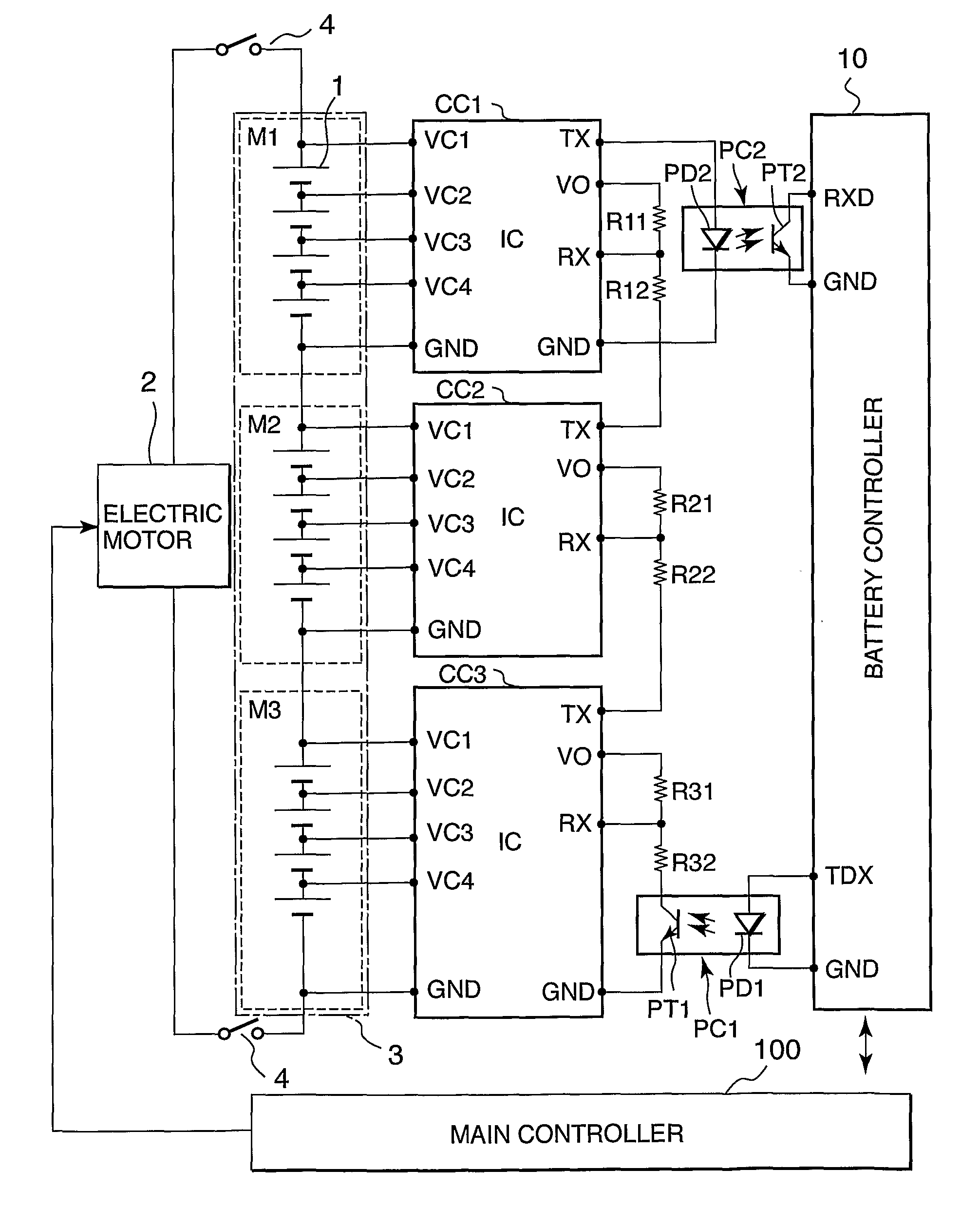
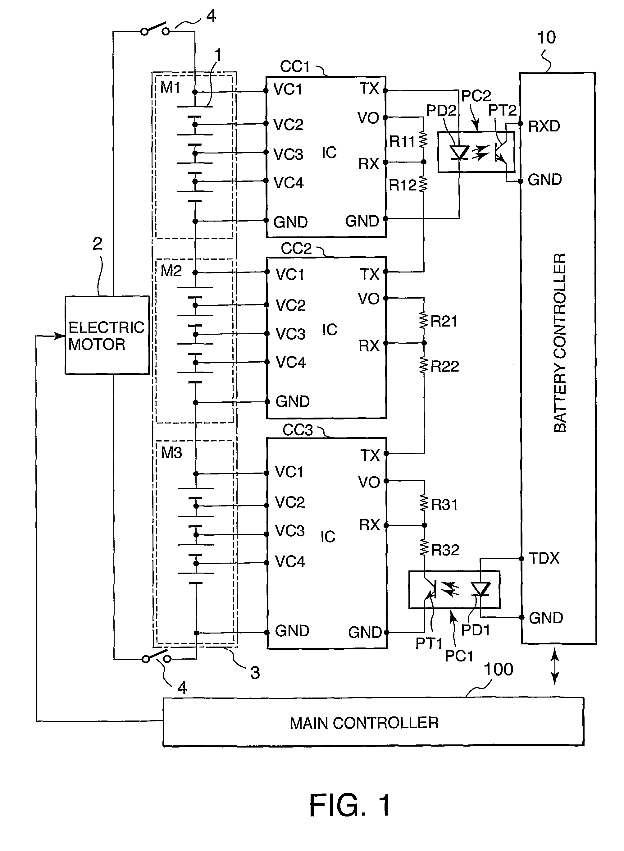
[0121]This embodiment is applied to a hybrid drive electric vehicle. The hybrid drive electric vehicle comprises two motive power sources, i.e. an electric motor 2 and an internal combustion engine. Herein, the electric motor 2 also functions as a starter motor for the internal combustion engine.

[0122]Referring to FIG. 7, the monitoring device comprises temperature sensors 7 that detect an atmospheric temperature of the battery modules M1-M3. Temperatures detected by the temperature sensors 7 are input into the battery controller 10 as signals via an independent signal circuit.

[0123]A cranking signal indicating that the electric motor 2 is operative, or in other words indicating cranking of the internal combustion engine, is input into the battery controller 10 from the electric motor 2.

[0124]On the basis of these signals, the battery controller 10 performs a battery module abnormali...


PUM


Abstract

A battery controller 10 outputs a voltage sampling and holding command signal to an integrated circuit CCn located at an upstream end of cascade connection of integrated circuits CC1-CCn such that integrated circuits CC1-CCn sample and hold output voltages of unit cells 1 grouped into battery modules M1-Mn. The battery controller 10, after confirming that the voltage sampling and holding command signal has been transmitted to an integrated circuit CC1 located at a downstream end of the cascade connection, outputs a transmission command signal to the integrated circuit CCn at the upstream end of the cascade circuit to transmit output voltages of the unit cells 1 held in the integrated circuits CC1-CCn to the battery controller 10. As a result, a time lag in the detection timings of output voltages of the unit cells 1 of the battery modules M1-Mn can be decreased.

Description

FIELD OF THE INVENTION[0001]This invention relates to a monitoring device for a plurality of battery modules, each of which comprises a plurality of unit cells.BACKGROUND OF THE INVENTION[0002]JP2003-070179A, published by the Japan Patent Office in 2003, proposes a monitoring device that detects a voltage of each unit cell in a plurality of battery modules, each of which comprises a plurality of unit cells.[0003]The monitoring device comprises integrated circuits (IC), each of which detects voltages of the unit cells in each of the battery modules. These integrated circuits are connected to a controller via a so-called cascade connection circuit, and information output from each integrated circuit is processed in the controller. The monitoring device comprises an entire output voltage detection circuit for detecting an entire output voltage of the battery modules and is configured to determine a state of the battery modules through a process of comparing the data obtained from the i...

Claims


Application Information

Patent Timeline
IPC IPC(8): G01R31/36G06F19/00B60K6/28H02J7/02
CPCG01R31/3658H02J7/0021H01M10/482H01M10/441B60L3/0046H04Q9/00B60L2240/545B60L2240/547B60L2250/10H04Q2209/823H04Q2209/30Y02T90/16B60L58/18G01R31/396B60L58/24B60L58/21B60L58/14Y02T10/70Y02E60/10H02J7/0013H02J7/0048H02J7/005G01R31/3835
Inventor KANEKO, KAZUMIIGUCHI, HIROFUMITAKANEZAWA, YUKI
Owner NISSAN MOTOR CO LTD
Why Eureka
Try Eureka