Monolithic metallic self-ligating bracket with locking catch devices

Inactive Publication Date: 2012-03-01
BEIJING SMART TECH
View PDF6 Cites 7 Cited by
  • Summary
  • Abstract
  • Description
  • Claims
  • Application Information

AI Technical Summary

Benefits of technology

[0020]The present invention is directed toward a monolithic metallic self-ligating bracket including a base, and two tie wings and at least one locking catch device placed on one surface of the base. There are slots in the middle of the tie wings extending in a generally mesial-distal direction, and the inner edges of the locking catch device towards the axis together with the slot form a concave to hold arch wire. The tie wings, the locking catch devices and the base are processed by integral shaping method. Compared with gland self-ligating brackets, the monolithic metallic self-ligating bracket of the present invention forms an arch wire concave by the locking catch devices and the slots in the tie wings. After the arch wire inserted to the archwire concave, the locking catch devices return to its original shape immediately, and the arm tips extending into the archwire concave of the locking catch devices enclasp the arch wire

Problems solved by technology

Traditionally, metal ligatures or elastic ligatures (O-ring elastic) are applied to fix the arch wire into the slot of the brackets, but there are several disadvantages of this method such as time consuming and inconvenience for clinical operation, high friction, and discomfort.
However, self-ligating brackets are still with limitations during clinical application.
For example, self-ligating brackets are difficult to be located precisely in adhesive process, because compared to the conventional twin-tie wing bracket, most self-ligating bracket are with quite different patterns: the structure of the self-ligating bracket is more complicated, and its twin-tie wings are inapparent, which may cause inconvenience for the orthodontists clamping and placing the bracket, result in the difficultly fit of the self-ligating brackets panels and the radian of the dentalface and imprecise bracket locating.
Imprecise bracket locating will increase the difficulty of precise teeth adjustment in the finishing stage of the treatment, lengthen the precise teeth adjustment period accordingly, and bring inconvenience to the clinical operation.
On the other hand, the design of some current self-ligating bracket is found unsatisfactory.
For example, if the slide closure or locking catch device opens under some unexpected situations, the brackets will lose their control of the arch wire that will influence the treatment effect and lengthen

Method used


Image

  • Monolithic metallic self-ligating bracket with locking catch devices
  • Monolithic metallic self-ligating bracket with locking catch devices
  • Monolithic metallic self-ligating bracket with locking catch devices

Examples


Example

Embodiment 1

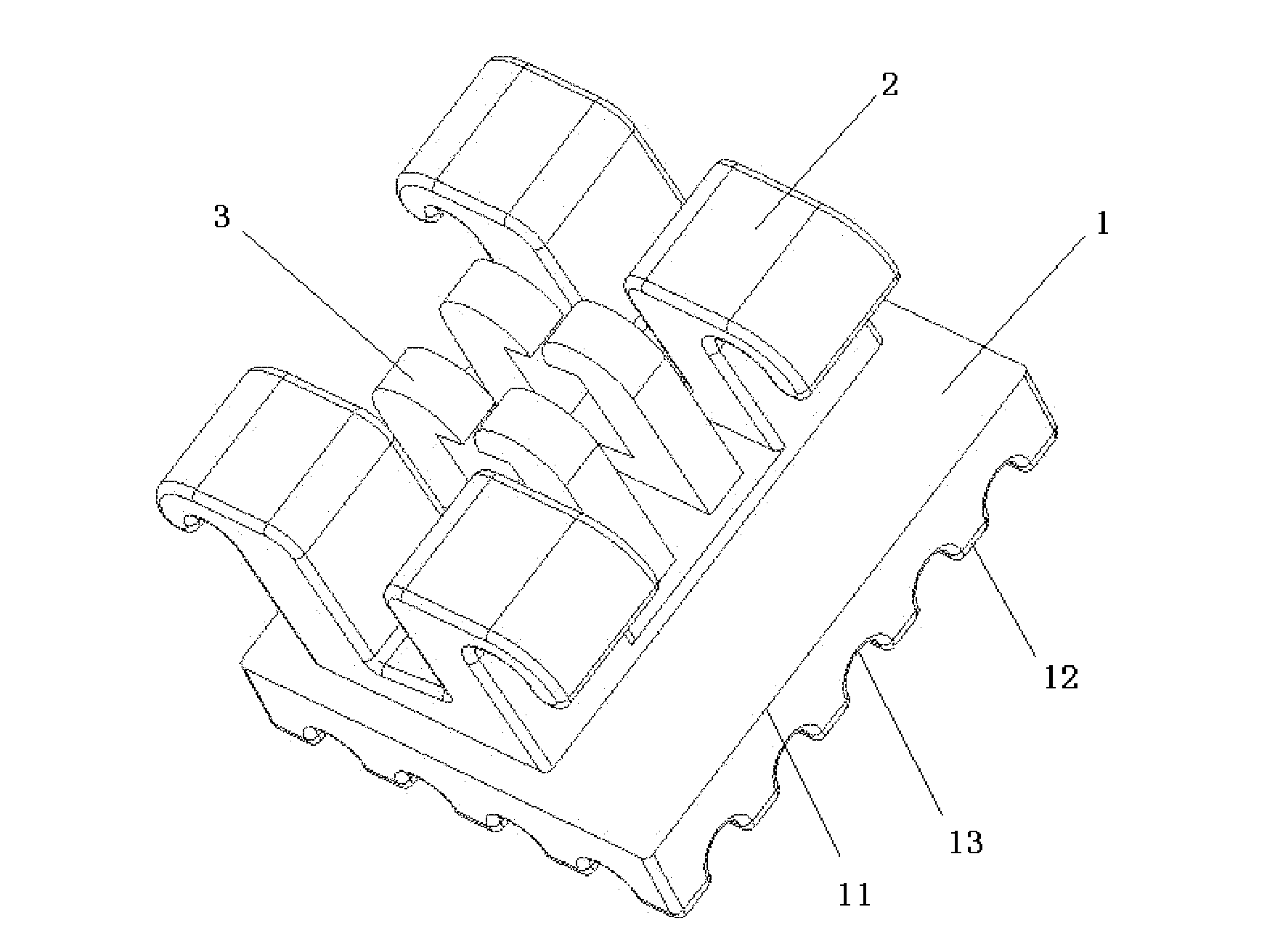
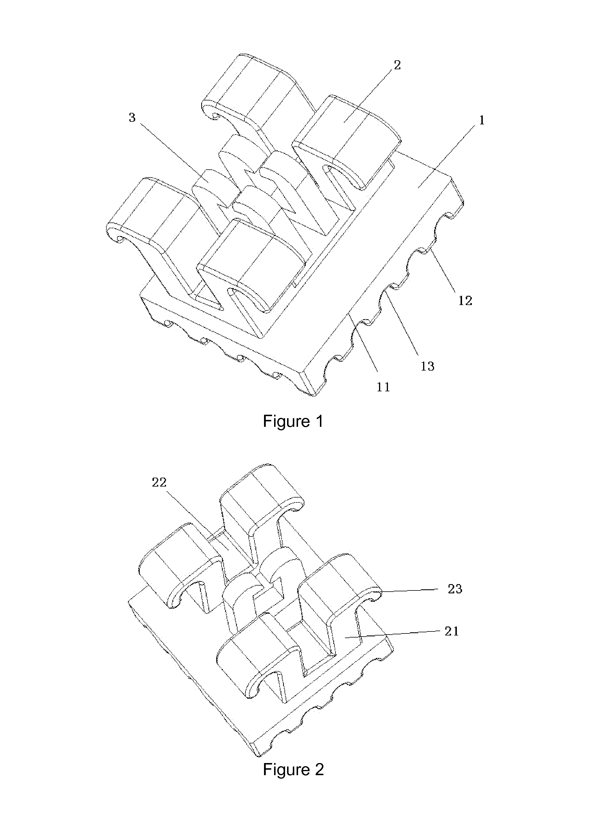
[0037]As shown in FIG. 1 and FIG. 2, the self-ligating bracket of present embodiment including base 1, two tie wings 2, 2N locking catch devices 3 (N is natural number), wherein tie wing 2 and locking catch devices 3 and base 1 are processed by integral shaping method such as metal casting, metal powder injection molding (MIM), linear cutting and so on. The self-ligating bracket is made of metallic material in its entirety, such as Nickel-Titanium alloy, Nickel-Titanium based alloys, Titanium based alloys, Co—Cr alloys or Stainless Steel. Base 1 is a board with generally cuboid shape, whose front side is surface 11, back side is the bonding surface 12, wherein surface 11 is a smooth plane, the bonding surface 12 is with a ravine like grooves 13 in favor for binder's inflow to enhance the retention force of the bracket. Two tie wings 2 are placed in a mesial and distal direction of the surface 11 respectively, wherein tie wing 2 includes a support 21 that connected with s...

Example

Embodiment 2

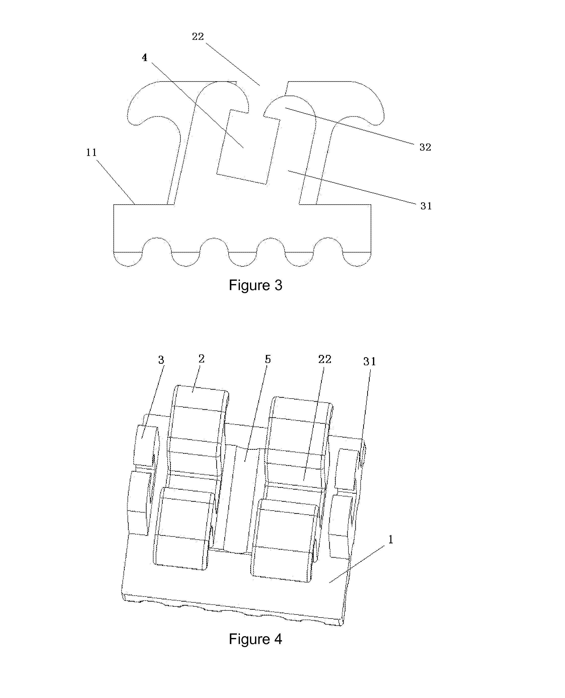
[0040]As showed in FIG. 4, on the basis of embodiment 1, the self-ligating bracket of the present embodiment is without the locking catch devices 3 that placed in the space between two tie wings 2, and there is a group of locking catch devices 3 placed on each external side of the two tie wings on the surface 11 along the slot 22 axis. The locking catch devices 3 of each group are symmetrically placed on the two sides of the axis of slot 22 and the two locking catch devices 3 of one group join up at the base of the trailing arm 31, the shape of the cavity between the two locking catch devices 3 is a roughly upturned “C” type with its mouth upward. The shape of the cavity between the two locking catch devices 3 is in conformity with the inner contour of the slot 22, the cavity and slot 22 form the archwire concave 4 together, which enhances the control and enclasping ability on an arch wire, and keeps the arch wire fixed without bounce off from the archwire concave 4 with...

Example

Embodiment 3

[0041]As showed in FIG. 5, on the basis of embodiment 1, the self-ligating bracket of the present embodiment is with a group of locking catch devices 3 placed on each external side of the two tie wings 2 on the surface 11 along the axis of slot 22. The two locking catch devices 3 of each group are symmetrically placed on the two sides of the axis of slot 22 and the two locking catch devices 3 of one group join up at the base of the trailing arm 31. The shape of the cavity between the two locking catch devices 3 is a roughly upturned “C” type with its mouth upward. The shape of the cavity between the two locking catch devices 3 is in conformity with the inner contour of the slot 22, the cavity and slot 22 form the archwire concave 4 together, which enhances the control and enclasping ability on a arch wire, and keeps the arch wire fixed without bounce off from the archwire concave 4 within certain limits.


PUM


Abstract

A monolithic metallic self-ligating bracket with a locking catch device is provided. The bracket includes a base, at least one tie wing and at least one locking catch device placed on one surface of the base. A slot in the middle of the tie wing extends in a generally mesial-distal direction. One end of a trailing arm connects with the base, and the other end of the trailing arm extends transversely toward the axis to form an arm tip, the inner edge of the trailing arm and arm tip towards the axis, together with the slot form an archwire concave. After the arch wire is inserted to the archwire concave, the locking catch device returns to its original shape, and the arm tip extending into the archwire concave of the locking catch device enclasps the arch wire, making the best use of the therapeutic force of the archwire.

Description

[0001]The entire disclosure of Chinese Patent Application No. 201020507699.8, filed Aug. 27, 2010 is expressly incorporated by reference herein.FIELD OF THE INVENTION[0002]The present invention is directed toward an orthodontic appliance of dentistry, more particularly, the present invention relates to a monolithic metallic self-ligating bracket with locking catch devices.BACKGROUND OF THE INVENTION[0003]Orthodontic treatment is an important branch discipline with a high level of specialization of dentistry, concerning with the treatment of malocclusions (improper bites), which may be a result of tooth irregularity, disproportionate jaw relationships, or both. Orthodontic treatment focuses on the treatment of the malformation of teeth, jaw bones and face, and provides the patient with a functionally improved bite by fixing an orthodontic appliance in the patient's oral cavity. Brackets are important parts of an orthodontic appliance, mainly bonded to patients' anterior, cuspid and b...

Claims


Application Information

Patent Timeline
IPC IPC(8): A61C7/30
CPCA61C7/30
Inventor BINGMIN, HUANGDONGLIANG, ZHANGLIN, LINHUA, CHEN
Owner BEIJING SMART TECH
Why Eureka
Try Eureka