Energy delivery systems and uses thereof

a technology of energy delivery and energy delivery system, applied in the field of energy delivery system, can solve problems such as collapsing tissue damage, and achieve the effects of optimizing energy delivery, maximizing flexibility or access to particular inner body locations, and optimizing rigidity and/or strength of devices

Inactive Publication Date: 2012-03-01
NEUWAVE MEDICAL
View PDF8 Cites 61 Cited by
  • Summary
  • Abstract
  • Description
  • Claims
  • Application Information

AI Technical Summary

Benefits of technology

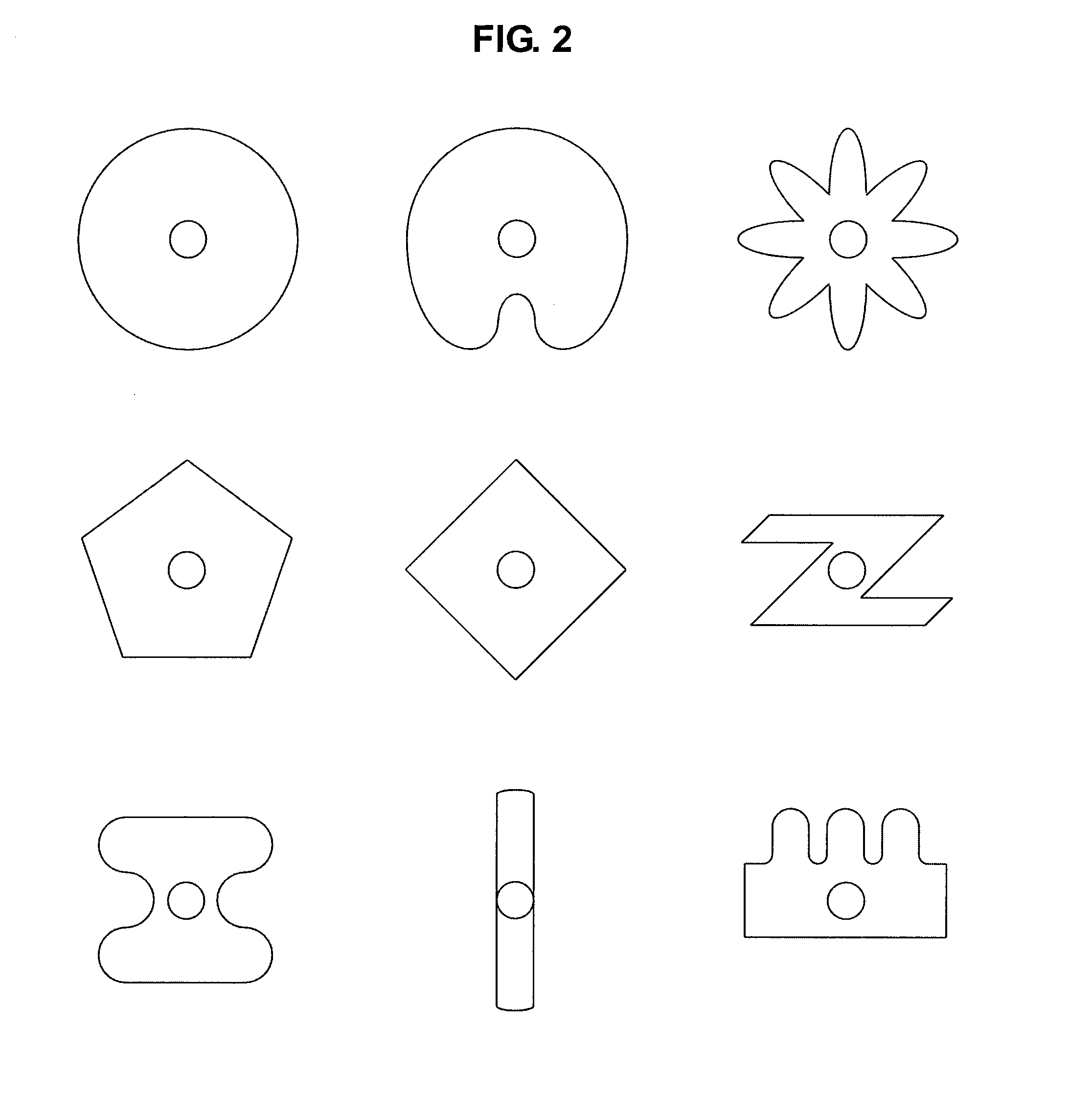
[0020]Likewise, in some embodiments, an antenna of the present invention has a non-circular cross-sectional shape along its length or for one or more subsections of its length. In some embodiments, the antenna is non-cylindrical, but contains a coaxial cable that is cylindrical. In other embodiments, the antenna is non-cylindrical and contains a coaxial cable that is non-cylindrical (e.g., matching the shape of the antenna or having a different non-cylindrical shape). In some embodiments, having any one or more components (e.g., cannula, outer shell of antenna, outer conductor of coaxial cable, dielectric material of coaxial cable, inner conductor of coaxial cable) possessing a non-cylindrical shape permits the creation of one or more channels in the device that may be used, among other reasons, to circulate coolant. Non-circular shapes, particularly in the outer diameter of the antenna also find use for certain medical or other applications. For example, a shape may be chosen to maximize flexibility or access to particular inner body locations. A shape may also be chosen to optimize energy delivery. A shape (e.g., non-cylindrical shape) may also be selected to maximize rigidity and / or strength of the device, particularly for small diameter devices.
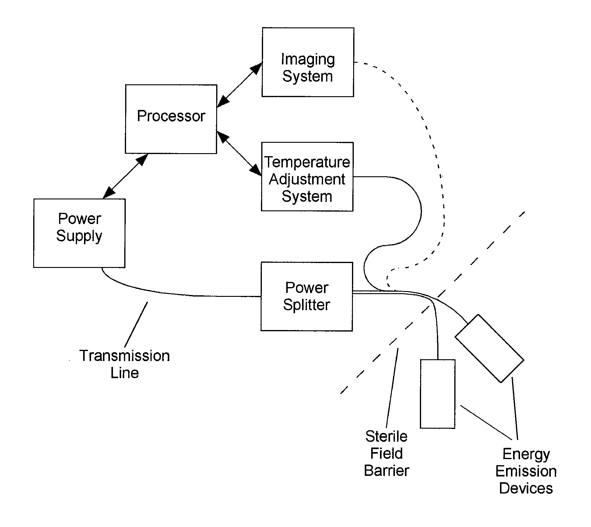
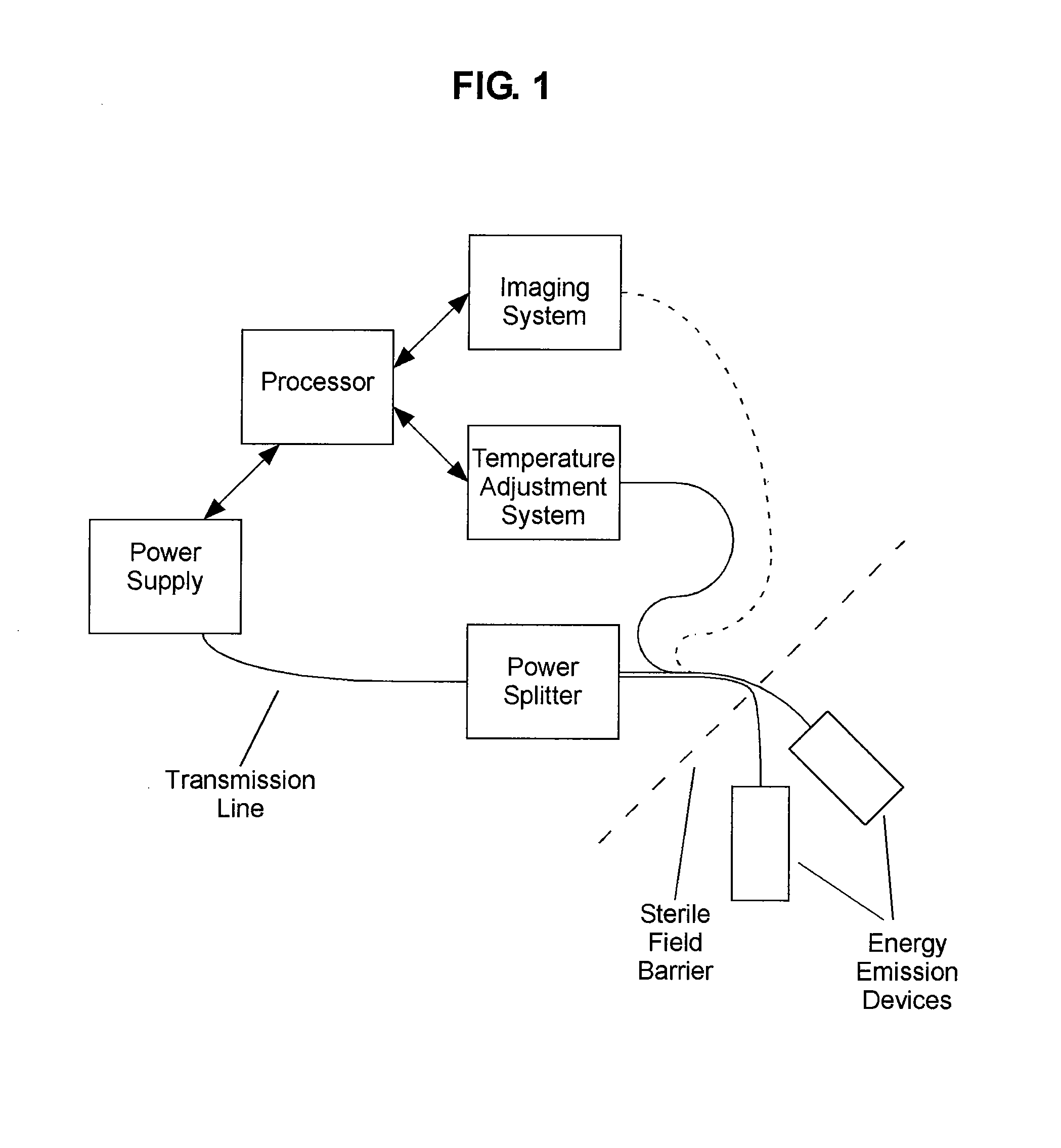
[0038]Additionally, integrated ablation and imaging systems are needed that provide feedback to a user and permit communication between various system components. System parameters may be adjusted during the ablation to optimize energy delivery. In addition, the user is able to more accurately determine when the procedure is successfully completed, reducing the likelihood of unsuccessful treatments and / or treatment related complications.

Problems solved by technology

One significant source of undesired overheating of the device is the dielectric heating of the insulator (e.g., the coaxial insulator), potentially resulting in collateral tissue damage.

Method used


Image

  • Energy delivery systems and uses thereof
  • Energy delivery systems and uses thereof
  • Energy delivery systems and uses thereof

Examples


example i

[0196]This example demonstrates the avoidance of undesired tissue heating through use of an energy delivery device of the present invention circulating coolant through coolant channels. The ablation needle shaft for all experiments was 20.5 cm. There was minimal cooling of the handle assembly indicating that handle-cooling effects were well-isolated. Temperature probes 1, 2 and 3 were located at 4, 8 and 12 cm proximal to the tip of the stainless needle (see FIG. 9). Temperature measurements were taken for 35% power measurement following insertion into a pig liver and 45% power measurement following insertion into a pig liver. For the 35% power measurement, Probe 4 was on the handle itself.

[0197]For the 45% power measurements, Probe 4 was located at the needle-skin interface, approximately 16 cm back from the stainless needle tip.

As shown in FIG. 10, treatment at 35% power for 10 minutes with anonymously high (6.5%) reflected power demonstrated maintenance of the device at a non-tis...

example ii

[0199]This example demonstrates generator calibration. Generator calibration was done by Cober-Muegge at the factory and was set to be most accurate for powers greater than 150 W. The magnetron behaved much like a diode: increasing cathode voltage did not increase vacuum current (proportional to output power) until a critical threshold was reached, at which point vacuum current increased rapidly with voltage. Control of the magnetron source relied on accurate control of the cathode voltage near that critical point. As such, the generator was not specified for powers from 0-10% and correlation between the output power and theoretical power percentage input was poor below 15%.

[0200]To test the generator calibration, the power control dial was changed from 0.25% in 1% increments (corresponding to theoretical output powers of 0-75 W in 3 W increments) and the generator's output power display was recorded and power output measured. The measured power output was adjusted for the measured ...

example iii

[0202]This example describes the setup and testing of an antenna during manufacturing. This provides a method for setup and tested in a manufacturing environment. The method employs a liquid, tissue-equivalent phantom rather than tissue.

[0203]From the numerical and experimental measurements already made on the antenna, it was known that changes in L2 of ˜1 mm will increase the reflected power from 2 is reasonable. Likewise, a tolerance of 0.5 mm on the length L1 is used, even though the total reflection coefficient depends less on L1 than L2.

[0204]Testing of the antenna tuning for quality control purposes can be achieved using a liquid 15 solution designed to mimic the dielectric properties of liver, lung or kidney (see, e.g., Guy A W (1971) IEEE Trans. Microw. Theory Tech. 19:189-217; herein incorporated by reference in its entirety). The antenna is immersed in the phantom and the reflection coefficient recorded using a 1-port measurement device or full vector network analyzer (VNA...


PUM


Abstract

The present invention relates to comprehensive systems, devices and methods for delivering energy to tissue for a wide variety of applications, including medical procedures (e.g., tissue ablation, resection, cautery, vascular thrombosis, treatment of cardiac arrhythmias and dysrhythmias, electrosurgery, tissue harvest, etc.). In certain embodiments, systems, devices, and methods are provided for treating a tissue region (e.g., a tumor) through application of energy. In certain embodiments, systems and devices of the present invention find use in combination with other medical devices (e.g., surgical devices, surgical tools; e.g., hemostats, blades, scalpels). In certain embodiments, more than one energy delivery system or device of the present invention may be employed simultaneously or sequentially (e.g., for cutting and coagulation procedures).

Description

CROSS-REFERENCE TO RELATED APPLICATION[0001]The present application claims priority to pending U.S. Provisional Patent Application No. 61 / 376,948, filed Aug. 25, 2010, the contents of which are incorporated by reference in its entirety.STATEMENT REGARDING FEDERALLY SPONSORED RESEARCH OR DEVELOPMENT[0002]None.FIELD OF THE INVENTION[0003]The present invention relates to comprehensive systems, devices and methods for delivering energy to tissue for a wide variety of applications, including medical procedures (e.g., tissue ablation, resection, cautery, vascular thrombosis, treatment of cardiac arrhythmias and dysrhythmias, electrosurgery, tissue harvest, etc.). In certain embodiments, systems, devices, and methods are provided for treating a tissue region (e.g., a tumor) through application of energy. In certain embodiments, systems and devices of the present invention find use in combination with other medical devices (e.g., surgical devices, surgical tools). In certain embodiments, mo...

Claims


Application Information

Patent Timeline
Patent Type & Authority Applications(United States)
IPC IPC(8): A61B18/18
CPCA61B18/1815A61B2018/00023A61B2018/1838A61B2018/00642A61B2018/00791A61B2018/00577
Inventor LEE, FRED T.SCHEFELKER, RICHARD W.BRACE, CHRISTOPHER LEE
Owner NEUWAVE MEDICAL
Why Eureka
Try Eureka