AC Electric Machine With Claw Poles

a technology of electric motors and claw poles, which is applied in the direction of synchronous machine details, windings, dynamo-electric components, etc., can solve the problems of low magnetic flux density and insufficient output of electric motors, and achieve the effects of improving the output and operation efficiency of electric motors, and increasing main magnetic flux and magnetic energy products

Active Publication Date: 2012-03-08
JING JIN ELECTRIC TECH CO LTD
View PDF5 Cites 18 Cited by
  • Summary
  • Abstract
  • Description
  • Claims
  • Application Information

AI Technical Summary

Benefits of technology

[0003]In order to solve the aforesaid problem, the present invention provides an AC claw-pole electric motor of a novel structure. The main magnetic flux of the AC claw-pole electric motor is generated by an electrically excited magnetic field and permanent magnets or by two magnetic fields of permanent magnets together. This can increase the main magnetic flux and the magnetic energy product of the electric motor, and can significantly improve the output and the operation efficiency of the electric motor when the belt-driven start / stop mild hybrid system of an automobile operates at a low speed.
[0004]Specifically, the present invention provides an alternating current (AC) claw-pole electric motor, mainly consisting of a casing, a stator connected with the casing, a rotor and two exciting parts. The rotor comprises a rotor shaft, a center magnetic yoke, a first side magnetic yoke, a second side magnetic yoke, and claw poles provided on the center magnetic yoke, the first side magnetic yoke and the second side magnetic yoke. The two exciting parts are respectively provided in spaces formed by the center magnetic yoke, the first side magnetic yoke, the second side magnetic yoke and the claw poles, and axially excited magnetic fluxes of the two exciting parts are opposite in direction. The AC claw-pole electric motor provided by the present invention can increase the main magnetic flux and the magnetic energy product of the electric motor, and can significantly improve the output and the operation efficiency of the electric motor when the belt-driven start / stop mild hybrid system of an automobile operates at a low speed.
[0005]Furthermore, in an AC claw-pole electric motor according to an embodiment of the present invention, the permanent magnet may be encased by a non-magnetically permeable sleeve to further ease the requirements on mechanical strength of the permanent magnet. The permanent magnet exciting part and the electrically exciting part are located at the two sides of the center magnetic yoke respectively to result in a larger distance between the permanent magnet and the stator section than that in the prior art, so heat generated by the stator section has less influence on the permanent magnet exciting part. This reduces the risk of demagnetization of the permanent magnet and improves the thermal stability of the electric motor.
[0006]Moreover, in the hybrid-excitation AC claw-pole electric motor according to the embodiment of the present invention, the magnetic flux generated by the permanent magnet is shunted into two paths when there is no electrically excited magnetic field applied in the electric motor, one of which is self-closed after passing through relevant parts of the electric motor and the other one of which flows towards the stator iron core and generates a radial magnetic flux, i.e., the magnetic flux of the permanent magnet that generates the radial magnetic flux in the iron core is shunted so as to decrease the no-load back electromotive force of the electric motor and ease the volt-ampere requirements on power electronic controllers in the belt-driven start / stop mild hybrid system of an automobile.

Problems solved by technology

In the claw-pole electric motor, the main magnetic flux is generated only by electrical excitation of the excitation winding, which leads to a very low magnetic flux density in the air gap between the stator and the rotor of the electric motor; and there is serious magnetic leakage between the adjacent and alternate claw poles, which causes insufficient output of the electric motor when the driving system operates at a low speed.

Method used


Image

  • AC Electric Machine With Claw Poles
  • AC Electric Machine With Claw Poles
  • AC Electric Machine With Claw Poles

Examples


embodiment 1

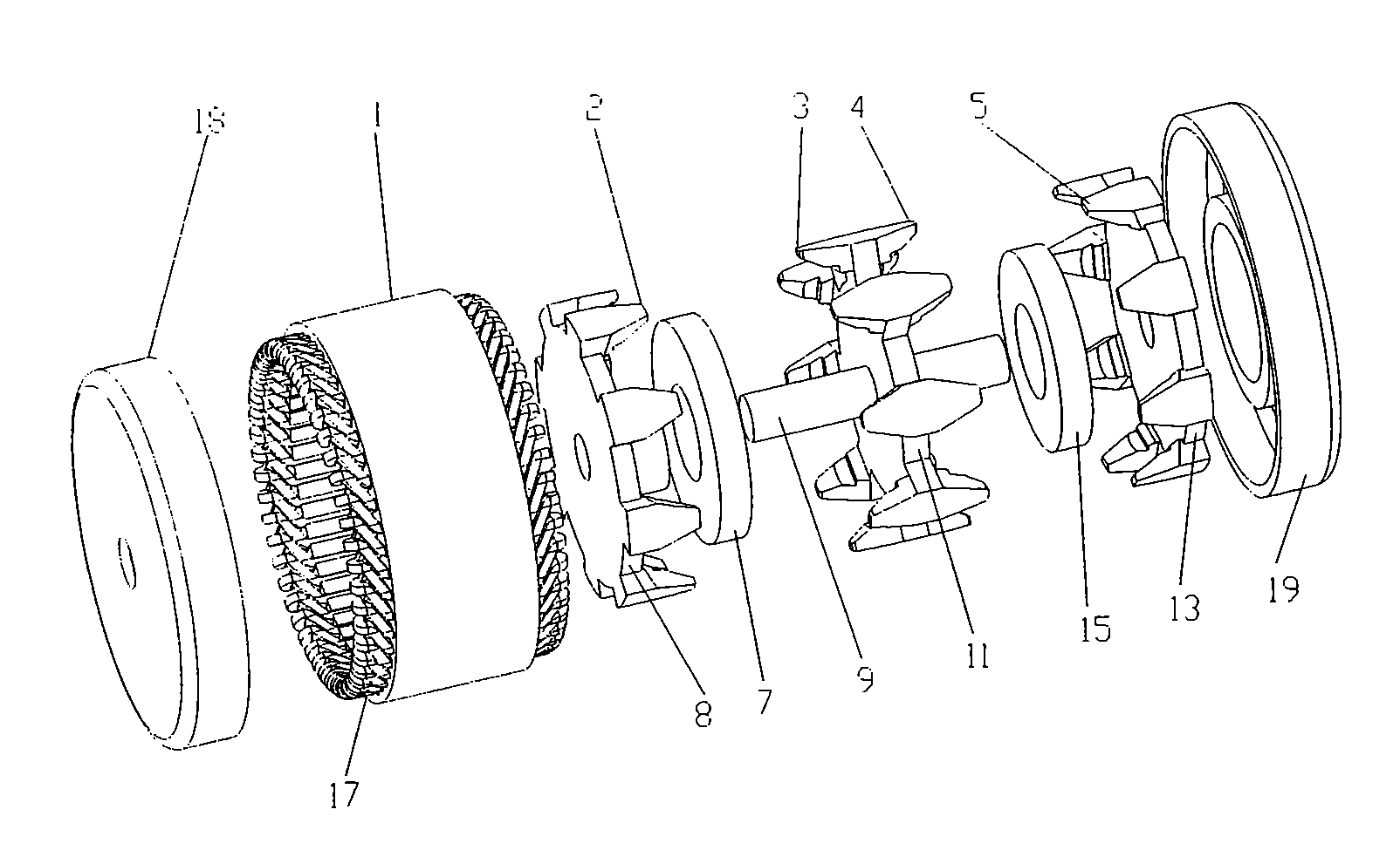
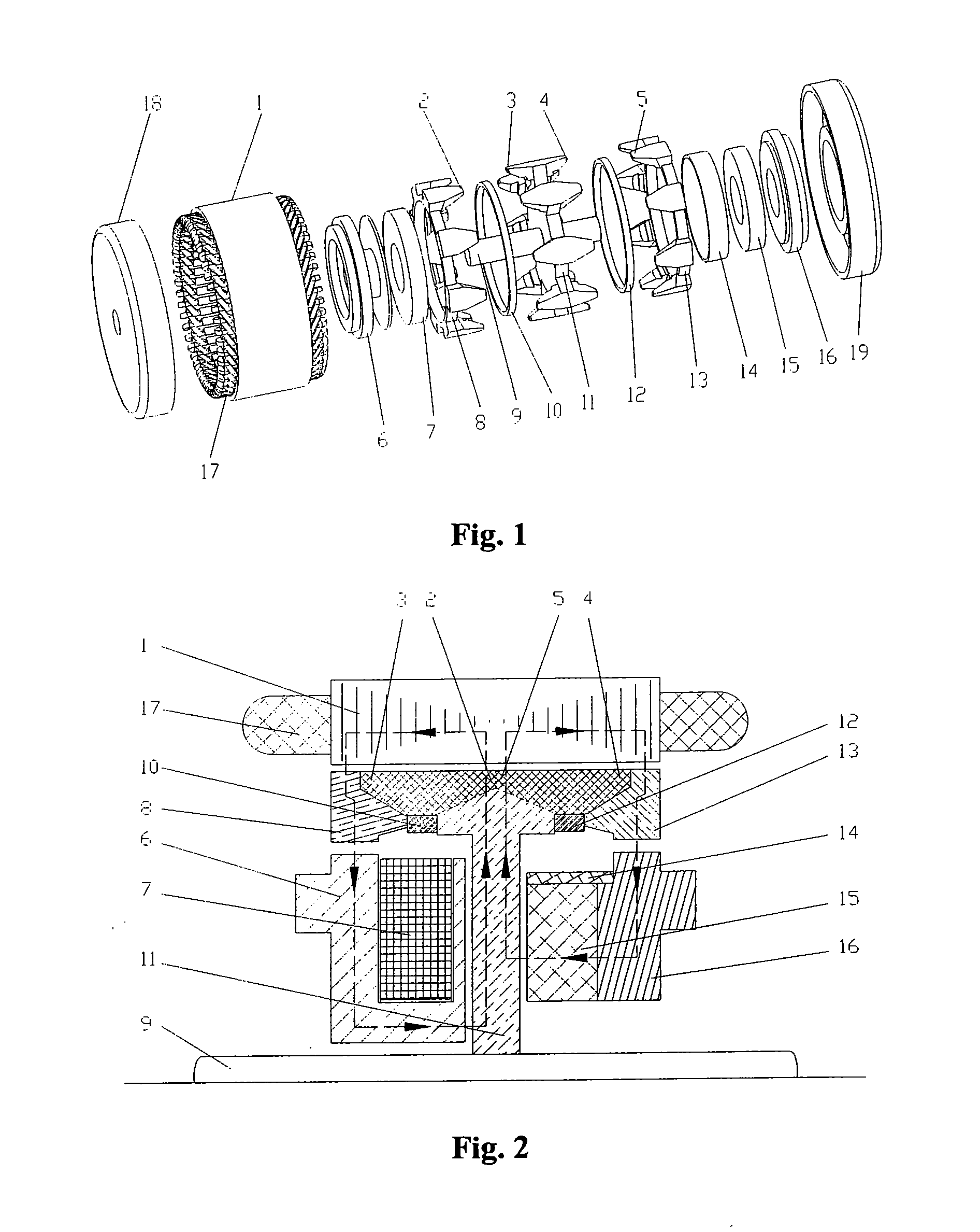
[0019]As shown in FIG. 1, the AC claw-pole electric motor of the present invention mainly consists of three sections, namely, a stator section, a rotor section and an exciting part.

[0020]The stator section comprises a stator iron core 1 and three-phase windings 17 wound on laminates of the stator iron core 1.

[0021]The rotor section comprises: a center magnetic yoke 11, a first center claw pole 3 and a second center claw pole 4 located at edges of the center magnetic yoke 11, a rotor shaft 9 located at a center of and perpendicular to the center magnetic yoke 11, a first side magnetic yoke 8 located at one side of the center magnetic yoke 11, a first side claw pole 2 located at an edge of the first side magnetic yoke 8, 110 a second side magnetic yoke 13 located at the other side of center magnetic yoke 11, and a second side claw pole 5 located at an edge of the second side magnetic yoke 13. Furthermore, the first center claw pole 3 and the first side claw pole 2 are adjacently and a...

embodiment 2

[0036]This embodiment differs from Embodiment 1 in that, the two exciting parts in the AC brushless claw-pole electric motor of this embodiment are both permanent magnet exciting parts, and other structures are all similar to those of Embodiment 1 and will not be described again herein.

[0037]FIG. 5 is a schematic showing the exploded structural view of an AC brushless claw-pole electric motor according to Embodiment 2 of the present invention. In FIG. 5, reference numerals 16′, 16″ represent permanent magnet exciting iron cores, and reference numerals 15′, 15″ represent annular permanent magnets. The permanent magnet exciting iron core 16′ is joined with the end cover 18 of the casing, and the annular permanent magnet 15′ is joined with the permanent magnet exciting iron core 16′. The annular permanent magnet 15′ is accommodated in a space formed by the center magnetic yoke 11, the first side magnetic yoke 8, the first side claw pole 2 and the first center claw pole 3. The permanent...

embodiment 3

[0040]This embodiment differs from Embodiment 1 in that the AC claw-pole electric motor of this embodiment is of a brush-type hybrid excitation structure, and both the electrically exciting part and the permanent magnet exciting part of this embodiment are fixed to the rotor and a brush and slip ring system (not shown) is needed.

[0041]FIG. 7 is a schematic showing the exploded structural view of an AC claw-pole electric motor according to Embodiment 3 of the present invention, and FIG. 8 is a schematic which shows a partially cross-sectional view illustrating a three-dimensional structure of the AC claw-pole electric motor shown in FIG. 7. As shown in FIG. 7, the center magnetic yoke 11, the first side magnetic yoke 8 and the second side magnetic yoke 13 are all of a round-disc form in this embodiment. The first side magnetic yoke 8 contacts closely with the center magnetic yoke 11, and the electrically exciting winding 7 is located between the first side magnetic yoke 8 and the cen...


PUM


Abstract

An AC claw-pole electric motor includes a casing, a stator connected with the casing, a rotor and two exciting parts. The rotor includes a rotor shaft (9), a center magnetic yoke (11), a first side magnetic yoke (8), a second side magnetic yoke (13), and claw poles (2, 3, 4, 5) provided on the center magnetic yoke (11), the first side magnetic yoke (8) and the second side magnetic yoke (13). The two exciting parts are respectively provided in spaces formed by the center magnetic yoke (11), the first side magnetic yoke (8), the second side magnetic yoke (13) and the claw poles (2, 3, 4, 5). The axial exciting magnetic fluxes of the two exciting parts are opposite in direction. Thus, the main magnetic flux and the magnetic energy product of the electric motor are increased, and the output and the operation efficiency of the electric motor at a low speed are improved.

Description

FIELD OF THE INVENTION[0001]The present invention relates to an alternating current (AC) electric motor, and more particularly, to an AC claw-pole electric motor.BACKGROUND OF THE INVENTION[0002]At present, belt-driven starter generator (BSG) electric motors used in belt-driven start / stop mild hybrid systems of automobiles commonly adopt claw-pole electric motors for both driving and power generation. A claw-pole electric motor mainly consists of a casing, a stator iron core connected with the casing, claw poles adjacent to and alternate with each other, a rotor magnetic yoke, an excitation winding, a rotary shaft, a carbon brush, and a copper slip ring and so on. In the claw-pole electric motor, the main magnetic flux is generated only by electrical excitation of the excitation winding, which leads to a very low magnetic flux density in the air gap between the stator and the rotor of the electric motor; and there is serious magnetic leakage between the adjacent and alternate claw p...

Claims


Application Information

Patent Timeline
Patent Type & Authority Applications(United States)
IPC IPC(8): H02K21/04
CPCH02K21/044H02K16/02
Inventor CAI, WEILIHENG, WANG
Owner JING JIN ELECTRIC TECH CO LTD
Why Eureka
Try Eureka