
Supply of a liquid-metal target in x-ray generation

Active Publication Date: 2012-03-08
EXCILLUM
View PDF3 Cites 25 Cited by
  • Summary
  • Abstract
  • Description
  • Claims
  • Application Information

AI Technical Summary

Benefits of technology

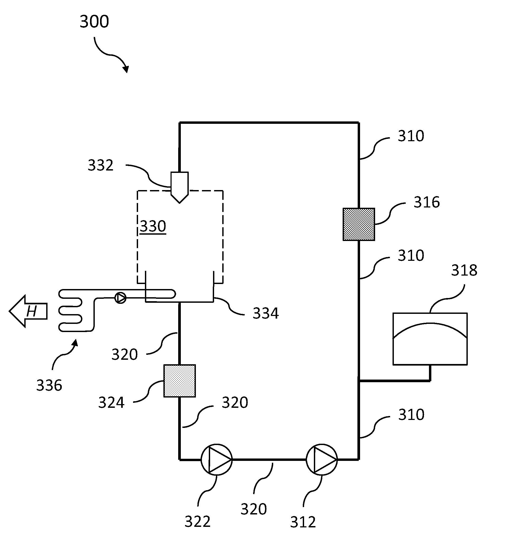
[0006]A general object of the present invention is to provide a closed-loop system for supply of liquid metal to an interaction region where an electron beam impacts the liquid metal to generate X-rays. It is envisaged that the present invention will provide prolonged operational times before X-ray generation must be interrupted for maintenance or service.
[0010]Leakage of metal is another potential challenge of a closed-loop system for providing the liquid-metal jet. The result of leakage may be that metal is permanently lost to the exterior of the system, but also includes the case of metal solidifying in parts of the system that are inaccessible. For example, a mist of suspended liquid droplets may be produced at the exit of the nozzle and at the point where the liquid jet impacts the liquid contained in the collecting receptacle. If such mist, which is relatively mobile, deposits on an inner wall of the low-pressure chamber, it will be more or less permanently lost from the circulation. Moreover, if the low-pressure chamber is a pumped vacuum chamber adapted to continuously evacuate gaseous or gas-suspended particles therein, an amount of liquid may be expelled from the system this way. Finally, seals, piping and pumps are all sources of potential leakage of liquid and therefore weak points of the circulation loop. From a user's point of view, leakage may release potentially toxic gas, necessitate expensive replenishment of liquid, shorten maintenance intervals (particularly the periods between cleaning of the X-ray output window), deteriorate performance by spoiling the vacuum conditions, and generally make operation of the associated X-ray source more difficult for continuous periods of time. These challenges are addressed and mitigated by the present invention.
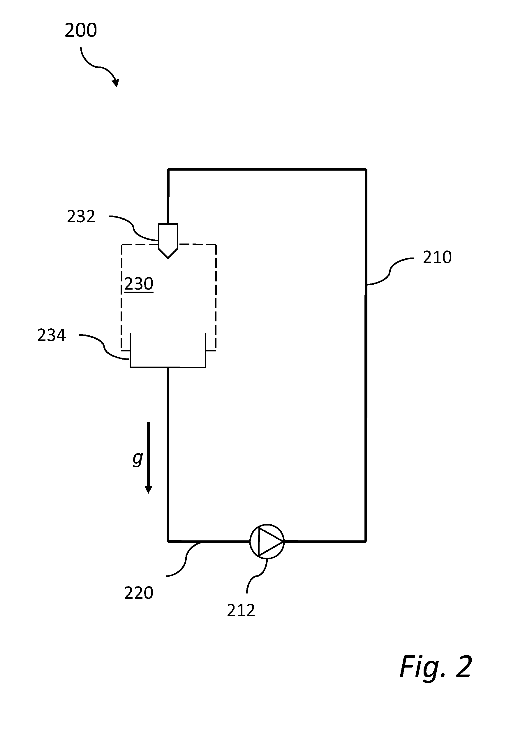
[0016]The pressure of the collected liquid metal is raised to a suction side pressure (inlet pressure) for the high-pressure pump, in a second portion of the closed-loop circulation system located between the collection reservoir and the high-pressure pump in the flow direction (i.e., during normal operation of the system, liquid metal flows from the collection reservoir towards the high-pressure pump). The inlet pressure for the high-pressure pump is at least 0.1 bar, preferably at least 0.2 bar, in order to provide reliable and stable operation of the high-pressure pump.The steps are then typically repeated continuously—that is, the liquid metal at the inlet pressure is again fed to the high-pressure pump which again pressurizes it to at least 10 bar etc.—so that the supply of a liquid metal jet to the interaction region is effected in a continuous, closed-loop fashion.
[0018]The step of raising the pressure of the collected liquid metal to a sufficient inlet pressure ensures good operating conditions for the high-pressure pump, enabling it to supply a steady high pressure to the nozzle and protecting it from losing its suction capacity. Preferably, the propagation speed of the liquid-metal jet through the vacuum chamber is at least 10 m / s. The liquid metal jet is generated so that the jet will be spatially continuous at the point where the electron beam impacts the metal jet. It is noted, however, that breakup of the jet beyond the point where the electron beam impacts the target jet is generally acceptable since such late breakup of the jet does not affect the generation of X-rays to any relevant extent; the possibility of such breakup does not influence the dimensioning of the nozzle.
[0022]As explained earlier, the X-ray generation process produces a considerable amount of excess heat. A high temperature may accelerate corrosion and other types of deterioration of the system. In order to remove the excess heat from the liquid metal there may be provided a cooler, such as a refrigerating coil thermally connected to the collection reservoir, adapted to discharge excess heat delivered by the electron beam to the outside the circulation system. Such cooler may be operated at a rate proportionate to the actual intensity of the electron beam with an aim of maintaining the liquid metal contained in the circulation system at a moderate set-point temperature, such as slightly above the melting point for the metal at issue. It should be understood, however, that the temperature of the liquid metal will vary through the different portions of the closed-loop circulation system.
[0027]In some implementations of the inventive system, the liquid metal may be passed through one or more filters during its circulation in the system. For example, a relatively coarse filter may be arranged between the collection reservoir and the high-pressure pump in the normal flow direction, and a relatively fine filter may be arranged between the high-pressure pump and the nozzle in the normal flow direction. The coarse and the fine filter may be used separately or in combination. Embodiments including filtering of the liquid metal are advantageous in so far as solid contaminants are captured and can be removed from the circulation before they cause damage to other parts of the system.

Problems solved by technology

On a technological level, supply of the liquid-metal jet in a closed-loop manner has been found to entail potential weaknesses.
The uniformity of the jet, in terms of speed, shape and thickness, may be dissatisfactory due to pressure variations caused by, e.g., the movement of pump pistons, intermittent mechanical obstruction by solid contaminant contained in the liquid, fluctuations of liquid levels in various parts of the system, and even loss of suction capacity of the pump.
Under some conditions, the jet may also become spatially discontinuous and break up into segments or droplets before a point where the electron beam impacts upon the jet, which would lead to complications with respect to the X-ray generation.

Method used


Image

  • Supply of a liquid-metal target in x-ray generation
  • Supply of a liquid-metal target in x-ray generation
  • Supply of a liquid-metal target in x-ray generation

Examples


Embodiment Construction

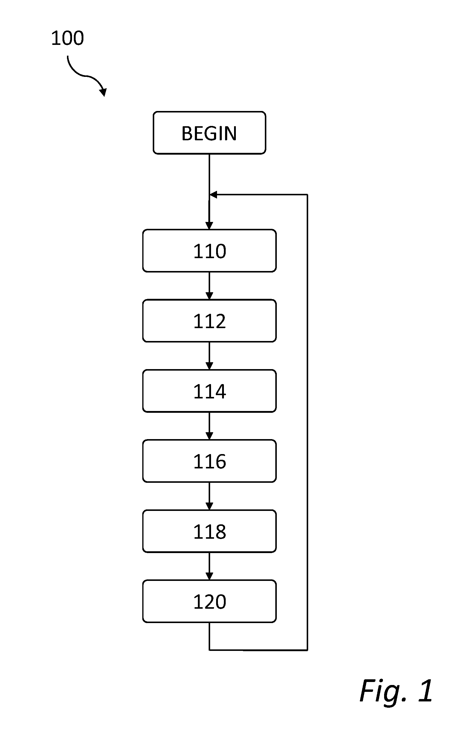
[0037]A method 100 for closed-loop supply of liquid metal, in accordance with a currently preferred embodiment of the invention, will now be described with reference to FIG. 1. For clarity and simplicity of this disclosure, the method will be described in terms of ‘steps’. It is emphasized that ‘steps’ are not necessarily processes that are delimited in time or separate from each other, and more than one ‘step’ may be performed at the same time in a parallel fashion. The intended outlook of this disclosure is that the ‘steps’ represent the different treatments that a liquid undergoes during its loop through a circulation system adapted to perform the method.

[0038]In step 110, the pressure of the liquid metal is raised to a high pressure. The high pressure should be sufficient in order for the liquid metal jet to obtain a high propagation speed in the vacuum chamber once injected from the nozzle. Typically, the high pressure will be at least 10 bar, preferably at least 50 bar and up ...


PUM


Abstract

Closed-loop circulation for providing liquid metal to an interaction region at which an electron beam is to impact upon the liquid metal to produce X-rays is presented. In a method according to the invention, the pressure of the liquid metal is raised to at least 10 bar using a high-pressure pump. The pressurized liquid metal is then conducted to a nozzle and ejected into a vacuum chamber in the form of a spatially continuous jet. After passage through the vacuum chamber, the liquid metal is collected in a collection reservoir, and the pressure of the liquid metal is raised to an inlet pressure, e.g. using a primer pump, suitable for the inlet of the high-pressure pump. The invention also relates to a corresponding circulation system and an X-ray source provided with such circulation system.

Description

FIELD OF THE INVENTION[0001]The present invention generally relates to liquid-metal targets, particularly for use in electron impact X-ray sources.TECHNICAL BACKGROUND[0002]X-rays have traditionally been generated by letting an electron beam impact upon a solid anode target. However, thermal effects in the anode limit the performance of the X-ray source. One way of mitigating the problems relating to overheating of the solid anode target has been to use a rotating solid anode.[0003]A second conventional approach is to direct the electron beam towards a liquid anode target, such as in the form of freely falling droplet or stream. U.S. Pat. No. 4,953,191 shows an X-ray source using as its anode a falling stream of liquid gallium, which is substantially flat and typically has a tangential velocity of about 2.0 m / s. In view of overheating, the power of an X-ray source of this type will be limited by the mass of gallium transported per unit time by the flowing stream. Spatial localizatio...

Claims


Application Information

Patent Timeline
IPC IPC(8): H01J35/02
CPCG03F7/70033H01J35/08H01J35/12H05G2/008H01J2235/1204H01J2235/1279H05G2/003H01J2235/082H01J35/112
Inventor HEMBERG, OSCARTUOHIMAA, TOMIOTENDAL, MIKAEL
Owner EXCILLUM
Learn More