Compact power converter with high efficiency in operation

a compact, power converter technology, applied in the direction of electric variable regulation, process and machine control, instruments, etc., can solve the problems of increasing the size of the power converter, reducing the efficiency of the power converter operation, and increasing the switching loss, so as to improve the structure of the power converter apparatus, high efficiency in operation, and compact size

Inactive Publication Date: 2012-03-22
DENSO CORP
View PDF3 Cites 26 Cited by
  • Summary
  • Abstract
  • Description
  • Claims
  • Application Information

AI Technical Summary

Benefits of technology

[0009]It is therefore an object to provide an improved structure of a power...

Problems solved by technology

Specifically, the reduction in size of the power converter equipped with the inductor is usually achieved by increasing a switching frequency, but the increasing of the switching frequency will result in an increase in switching loss, which leads to a decrease in efficiency in operation of the power converter.
The use of the additional passive components, however, results in an increase in size of the power converter.
Therefore, when the current flowing through the inductor is small, it will cause the rate at which the voltage charged in the capacitor changes to drop, thus resulting in an increased time required for the current to flow to the second current flow controlling component or a failure in elevating the voltage at the high-potential terminal of the first current flow controlling component up to that at the high-potential terminal of the second current flow controlling component.
This results in loss of the operation of the switching circui...

Method used


Image

  • Compact power converter with high efficiency in operation
  • Compact power converter with high efficiency in operation
  • Compact power converter with high efficiency in operation

Examples


first embodiment

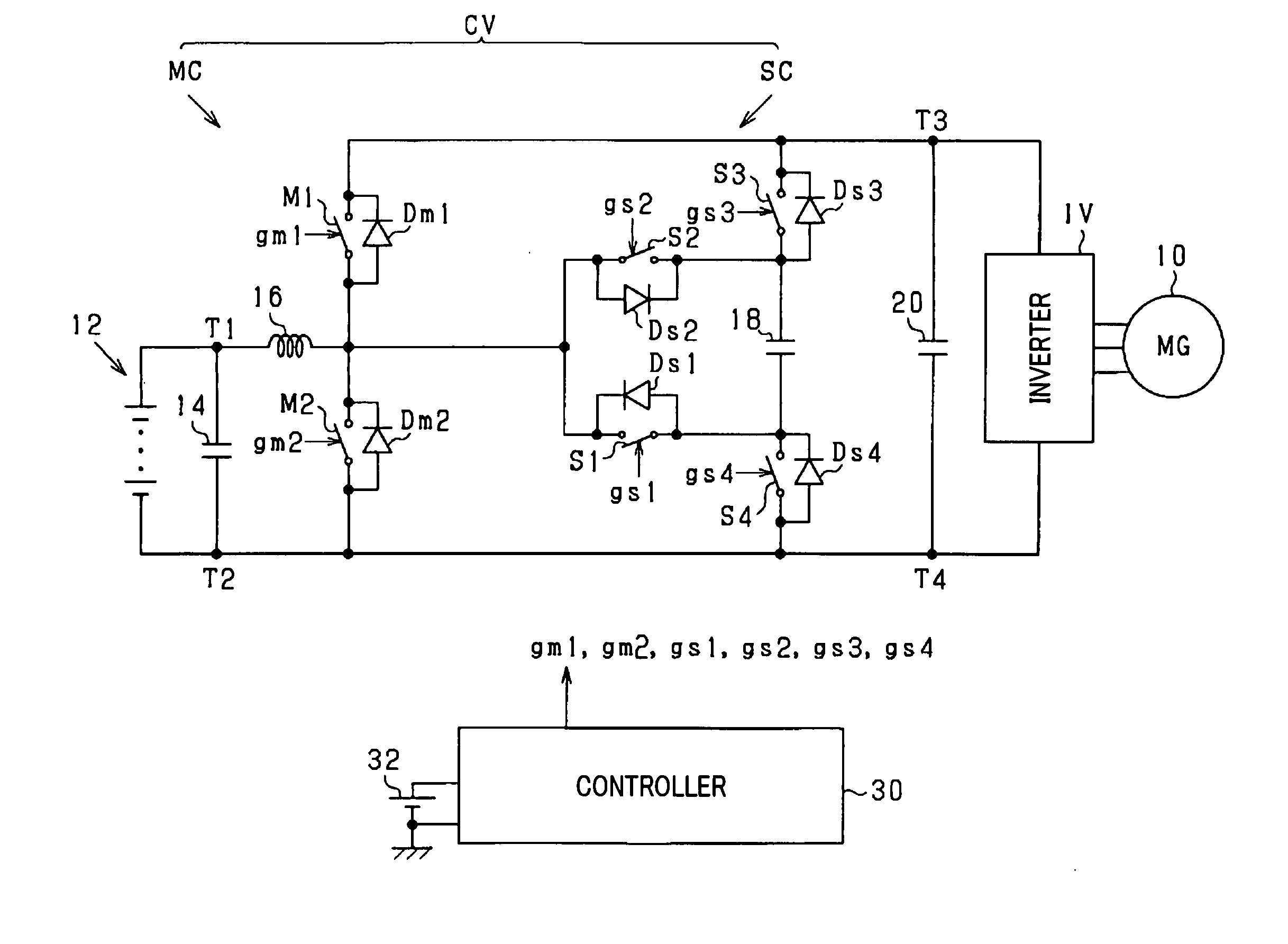
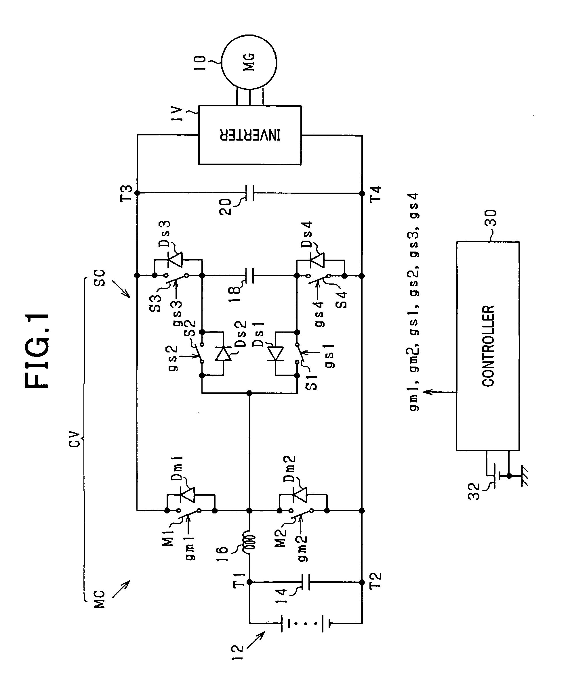
[0047]Referring to the drawings, wherein like reference numbers refer to like parts in several views, particularly to FIG. 1, there is shown a converter control system designed to control an operation of a power converter CV which is used in driving an main engine mounted in an automotive vehicle.

[0048]A motor-generator 10 is used as the main engine of the vehicle and has an output shaft (i.e., a rotating shaft) connected mechanically to driven wheels of the vehicle. The motor-generator 10 is joined electrically to a high-voltage battery 12 and a capacitor 14 through an DC-AC converter an inverter IV) and the converter CV. The high-voltage battery 12 is a secondary cell (also called a storage battery) whose terminal voltage is higher than one hundred volts.

[0049]The converter CV is equipped with a typical chopper circuit as a main circuit MC. The main MC consists essentially of a series-connected assembly of main switches M1 and M2, an inductor 16 connecting between a joint of the ...

second embodiment

[0070]The converter control system of the second embodiment will be described below.

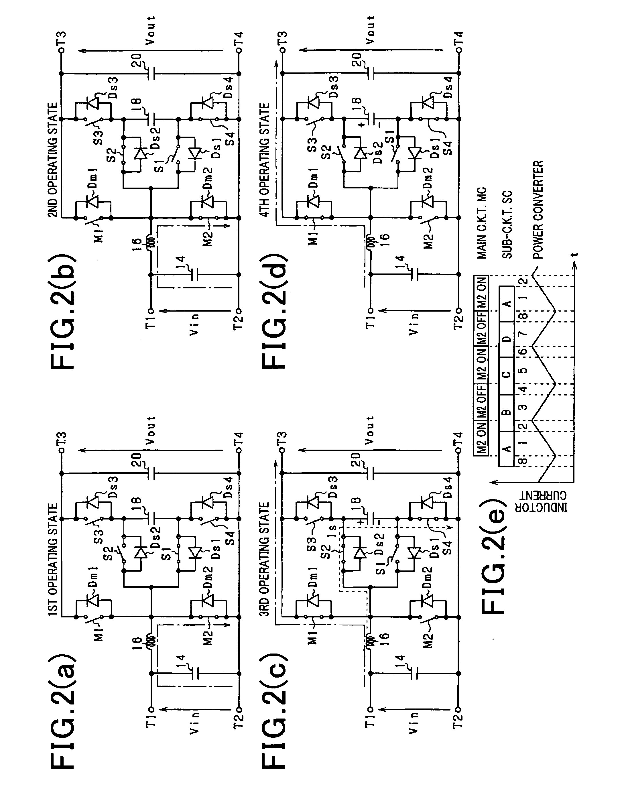
[0071]In the converter control system of the first embodiment, when the electrical energy charged in the inductor 16 in the power running made is not greater than that in the snubber capacitor 18 charged until the output voltage Vout of the converter CV, it is impossible to make the electric current flow through the diode Dm1 (i.e., the main switch M1) in the operating state B. In this condition, the switching loss occurs when the operating states of the sub-switches S1 and S3 are changed to connect the snubber capacitor 18 parallel to the main switch M1.

[0072]The energy to be charged in the snubber capacitor 18 is proportional to an electrostatic capacity or capacitance thereof and thus may be made to be smaller than the energy to be charged in the inductor 16 by decreasing the capacitance of the snubber capacitor 18. When the energy of the inductor 16 is much great, such decreasing of the capacitan...

fourth embodiment

[0085]FIG. 8 is a flowchart of a sequence of logical steps or program to be executed by the controller 30 of the converter control system of the fourth embodiment to control operations of the sub-circuit SC during the power running mode of the converter CV which include a special operation, as described below, to be executed when the current flowing through the inductor 16 is small. The program is to be executed at a regular interval.

[0086]After entering the program, the routine proceeds to step S20 wherein it is determined whether a given period of time has passed or not after the main switch M2 is turned off. This determination is made for determining whether the time when the operating state B or D is to be entered has been reached or not. The given period of time is preferably selected to be longer than or equal to the time required for the main switch M2 to be turned on in response to the on-signal from the controller 30. If a YES answer is obtained, then the routine proceeds t...


PUM


Abstract

A power converter including a main circuit and a sub-circuit. The main circuit serves as a step-up/down chopper circuit including a series-connected assembly of main switches, an inductor coupled to a joint of the main switches, and a capacitor connected in parallel to the series-connected assembly. The sub-circuit is designed to establish the soft-switching and includes a snubber capacitor, a first sub-switch coupled to the joint of the series-connected assembly and a negative terminal of the snubber capacitor, a second sub-switch coupled to the joint and a positive terminal of the snubber capacitor, a third sub-switch coupled to the positive terminal of the snubber capacitor and a high-potential terminal of the main circuit, and a fourth sub-switch coupled to the negative terminal of the snubber capacitor and a low-potential terminal of the main circuit.

Description

CROSS REFERENCE TO RELATED DOCUMENT[0001]The present application claims the benefit of priority of Japanese Patent Application No. 2010-210478 filed on Sep. 21, 2010, the disclosure of which is incorporated herein by reference.BACKGROUND OF THE INVENTION[0002]1. Technical Field[0003]The present invention relates generally to a power converter equipped with a first current flow controlling component which has an open / close function to open or close a current flow path and a second current flow controlling component which has at least one of the open / close function and a rectifying function to permit a flow of current only in one direction and is connected in series with the first current flow controlling component between a high-potential terminal and a low-potential terminal across which voltage is applied and an inductor coupled to a joint of the first and second current flow controlling components.[0004]2. Background Art[0005]Power converters equipped with an inductor are usually ...

Claims


Application Information

Patent Timeline
IPC IPC(8): H02M3/335
CPCH02M1/34Y02B70/1491H02M2001/342H02M3/1582Y02B70/10H02M1/342H02M7/4837
Inventor YAGYU, KEISUKEUMETANI, KAZUHIRO
Owner DENSO CORP
Why Eureka
Try Eureka