Driving Motor

a driving motor and motor body technology, applied in the field of motors, can solve the problems of noise generated by the driving motor, the rust of the components, and the insulation of the electric devices such as the armature, and achieve the effects of promoting a decrease of the temperature of the whole driving motor, excellent thermal conductivity, and easy dissipation of heat generated by the stator assembly

Inactive Publication Date: 2012-03-29
VALEO JAPAN CO LTD
View PDF8 Cites 17 Cited by
  • Summary
  • Abstract
  • Description
  • Claims
  • Application Information

AI Technical Summary

Benefits of technology

[0032]Thus, according to these inventions, the metal housing that contains at least the 
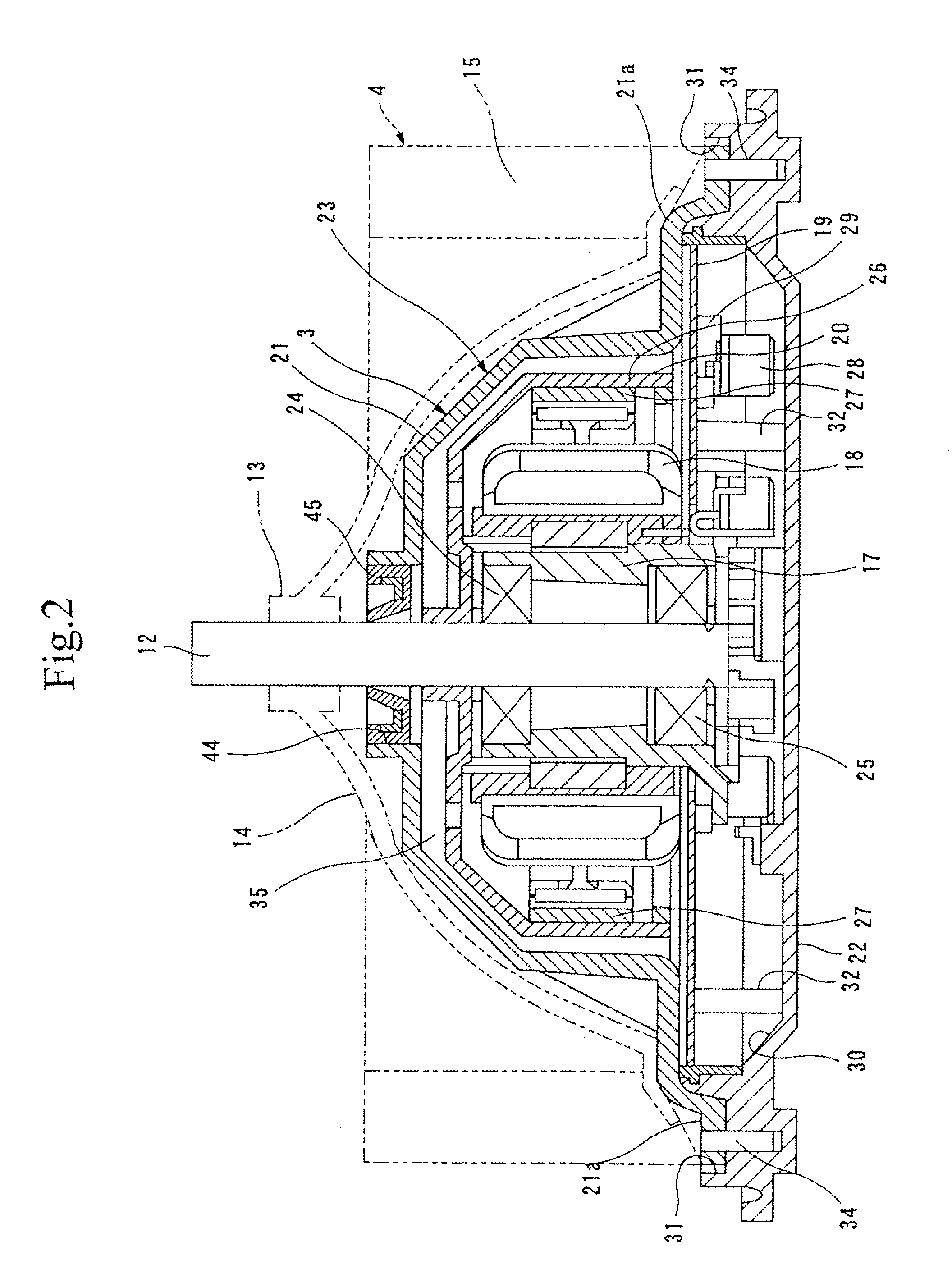
stator assembly covers the stator assembly from above like an umbrella shape; it is possible to provide the stator assembly with a water-proof function. In addition, since the housing which is made of metal of excellent thermal conductivity contains the stator assembly in it and the external surface of it is exposed to an air duct of a case such as a blower case, the heat from the stator assembly is transmitted to the housing, and the heat from the control circuit-board is also transmitted to the housing. Accordingly, the external surface of the housing faces the air duct of the case, heat generated from the stator assembly can be easily dissipation from the external surface of the housing. As a result, it is possible to promote a decrease of a temperature of the whole driving motor. This eliminates a need of a heat dissipation device such as a heat sink, and thus, the driving motor can be made compact and manufacturing cost of the motor can be reduced while keeping excellent heat dissipation.
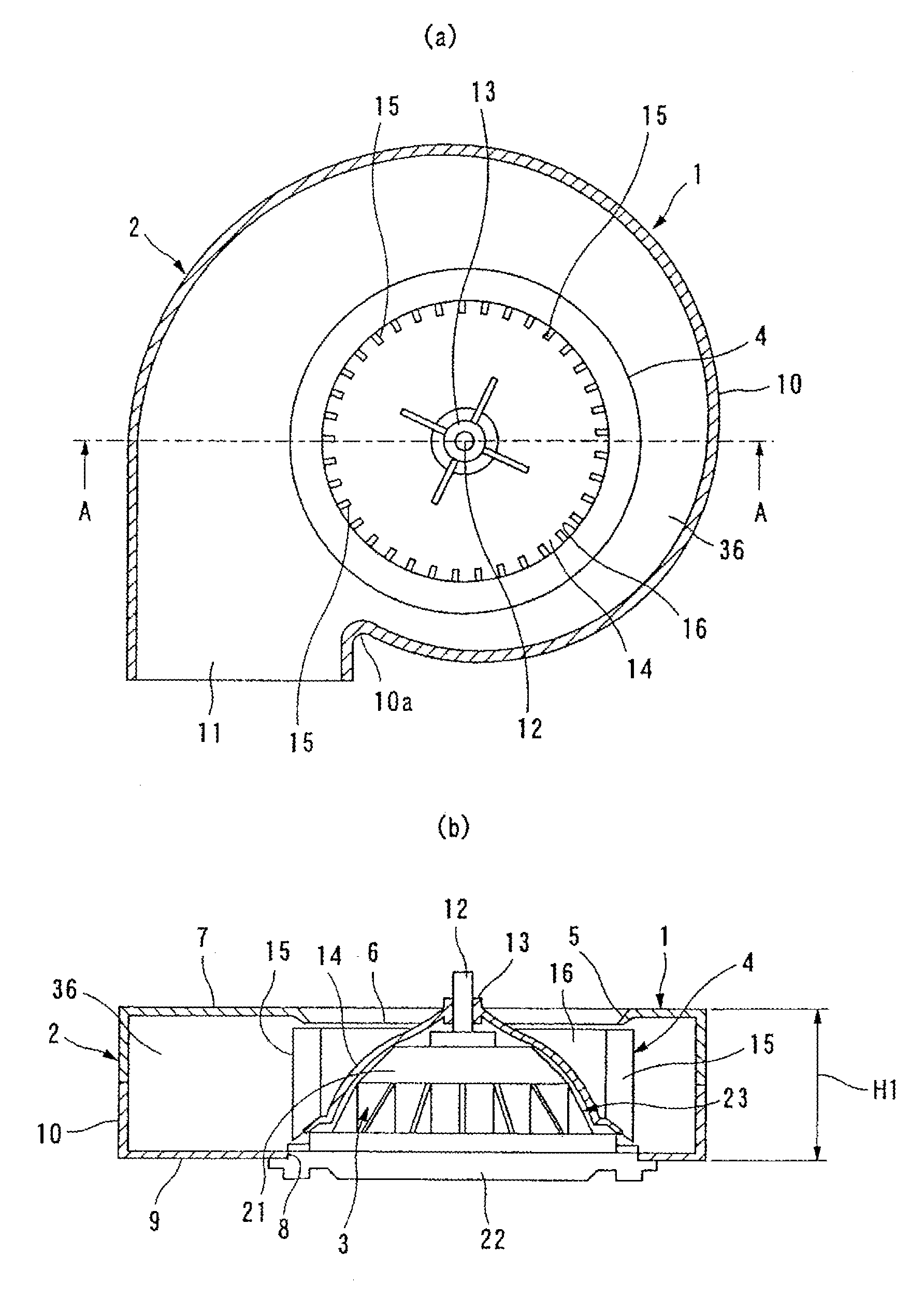
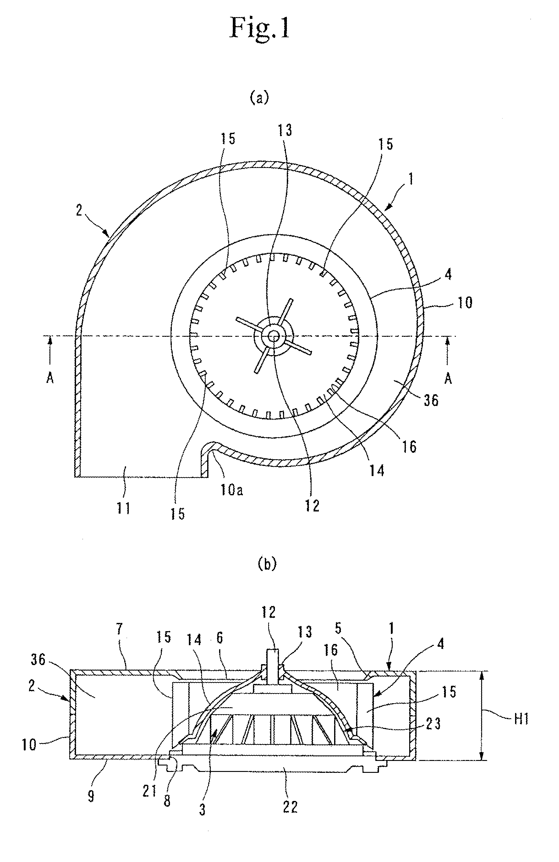
[0033]In particular, according to the invention described in claim 2, all the components arranged below the flange in the conventional driving motors are arranged upper side of the flange, and therefore, a need of a lower case attached at a lower portion of the flange in the conventional driving motors can be eliminated. As a result, the lower portion of the driving motor can be formed in a flat shape, and the size in the axial direction of the rotating shaft of the driving motor can be relatively made smaller by the thickness of the lower case of the conventional driving motors. Thus, it is possible to achieve a compact-sized driving motor, and even when the blower unit is installed in the duct, it is possible to prevent one portion of the driving motor from protruding to outside the duct, which results in improvement of the driving motor, as well as of the blower unit, in terms of layout.
[0034]Particularly, according to the inventions described in claims 3 and 4, the control circuit-board is also contained in the housing, and thus, it is possible to provide the control circuit-board with a water-proof function, which enables an elimination of a particular need of preparing a control circuit-board mounting space for installing the control circuit-board. Particularly, according to the inventions described in claims 3 and 4, although the heat from the control circuit-board is also transmitted to the housing, but the external surface of the housing is exposed to an air duct of the case, and thus, it is possible to dissipate the heat generated by the control circuit-board from the external surface of the housing. From this point, a need of a heat dissipation device such as a heat sink is eliminated. Thus, it is possible to further make the driving motor compact and reduce its manufacturing cost while keeping and improving the heat dissipating characteristic of the driving motor.
[0035]Particularly, according to the invention described in claim 5, since the gap between the first opening of the housing and the rotating shaft are air-tightly covered by interposing a elastic ring member, there is no gap between the first opening of the housing and the rotating shaft. As a result, it is possible to prevent water such as rain water from entering the motor interior-space through the gap, and it is also possible to prevent the transmission of the rotation vibration from the rotating shaft to the housing because the elastic ring member can attenuate the vibration.
[0036]Particularly, according to the invention described in claim 6, it is possible to prevent water such as rain water from entering the motor interior-space through a gap between the first opening of the housing and the rotating shaft even when the elastic ring member is not provided. Thus, the need of the elastic ring member can be eliminated, and the component count of the driving motor can be reduced. As a result, it is possible to reduce a manufacturing cost of the driving motor.
[0037]Particularly, according to the invention described in claim 7, the elastic mounting member that is inserted in the first opening can attenuate the transmission amount of the vibration component, and therefore, it is possible to inhibit the transmission of the vibration component from the vibration source to the flange.

Problems solved by technology

Moreover, it is known that when an external air introducing mode is selected in the blower unit of the vehicle air conditioner and the external air is introduced from outside the vehicle interior, in case of rain, a misty rain water together with the external air enters the blower so that water drops adhere to electric devices such as an armature, contained in the driving motor and give rise to a problem of the insulation of the electric devices such as an armature, or a problem of rust such as in the component parts.
If the two vibration components, magnetic vibration and vibration due to precession, are kept as it is, noise will be generated from the driving motor.

Method used


Image

  • Driving Motor
  • Driving Motor
  • Driving Motor

Examples


Embodiment Construction

[0060]Hereinafter, embodiments of the present invention will be described with reference to the accompanying drawings.

[0061]A blower unit 1 shown in FIG. 1 is situated in downstream of a battery for cooling the battery (not shown) and is used to inhales the heated air from the battery and to dissipate outside. Here, the blower unit 1 is designed for a small air volume, and includes a scroll-shaped blower case 2, a driving motor 3, and a multi-blade fan 4.

[0062]The blower case 2 is made of resin or the like, and includes: an upper side wall 7 having an opening 6 where a bell mouth 5 is formed integrated or separately; a lower side wall 9 that is arranged to face the upper side wall 7 at a predetermined interval and having therein a motor insertion hole 8 into which the driving motor 3 is installed; and an outer peripheral wall 10 situated to connect outer peripheral edges of the upper side wall 7 and the lower side wall 9 while providing a exhausting outlet 11 between them. The outer...


PUM


Abstract

Provided is a driving motor that will meet the requests of making the length of a rotating axis of the driving motor to be shorter in the axial direction, and which will also have waterproof, vibration resistance, and soundproof characteristics. In this driving motor (3); a motor interior-space (35) is formed by a housing (21) that has a first and second opening and which is formed to be cylinder shaped, and a flange (22) that blocks the second opening of this housing (21); and a stator assembly (18), a rotor assembly (20), a lower-side end section of the rotating axis (12) that has been placed lower than the flange (22) up until now, and a control circuit-board (19) are all made to be contained in this motor interior-space (35). Furthermore, a ring-shaped elastic member (45) is made to interpose between the upper-side end section of the rotating axis (12) and the first opening of the housing (21); and the lower-side end section of the rotating axis (12), the stator assembly (18), and the rotor assembly (20) are made to be fixed to the flange (22) through a mounting elastic member (59).

Description

TECHNICAL FIELD [0001]The present invention relates to a motor for driving a predetermined air-conditioning device such as a fan, where the motor being housed in a case with an air flow duct, such as a blower case of a blower unit, which may configure a vehicle air conditioner.BACKGROUND ART [0002]In recent years, there is a need for a more efficient driving motor for a blower, smaller than a conventional motor, for a vehicle air conditioner or a ventilation device for a hybrid vehicle. Thus, there is required development of a driving motor having excellent water-proof and heat releasing characteristics, having a smaller size along the axial direction of a rotating shaft of a blower, and reducing the manufacturing cost.[0003]In this case, for example, a vehicle-mounted blower equipped with a brushless motor as mentioned in Patent Document 1 is already known. The vehicle-mounted blower disclosed in Patent Document 1 is provided with a brushless motor that rotates a blower fan, a cool...

Claims


Application Information

Patent Timeline
Patent Type & Authority Applications(United States)
IPC IPC(8): H02K5/22H02K9/22
CPCF04D25/08F04D29/668H02K5/04H02K5/10H02K5/18H02K5/20H02K7/14H02K11/0073F04D25/068H02K5/22H02K5/24H02K11/33F04D25/0613H02K5/207
Inventor OI, SHINICHIJITSUKAWA, HIROKIHORIUCHI, KAZUYOSHIHAYASHI, NAOTO
Owner VALEO JAPAN CO LTD
Why Eureka
Try Eureka