Capacitive sensor with active shield electrode

a shield electrode and capacitive sensor technology, applied in the direction of resistance/reactance/impedence, pulse technique, instruments, etc., can solve the problems of noise immunity and electromagnetic compatibility conflicting with shielding requirements, and achieve the effect of increasing sensitivity

Inactive Publication Date: 2012-03-29
KOPIN CORPORATION
View PDF18 Cites 86 Cited by
  • Summary
  • Abstract
  • Description
  • Claims
  • Application Information

AI Technical Summary

Benefits of technology

[0002]Capacitive touch sensors are replacing switches, buttons, and knobs in new consumer electronics applications. The most famous is perhaps the circular dial on the Apple® iPod, but capacitive sense inputs are now common even on more mundane products, such as household appliances. Advantages of these touch inputs include reliability (no moving parts), lower manufacturing costs, operation in wet or dusty environments, and stylish design.
[0007]FIG. 1 illustrates a capacitive touch sensor, with finger capacitance CF and parasitic capacitance CP. taken from reference [3]. The finger capacitance CF increases as the finger approaches the sensor. The sensing circuit measures total capacitance CTOT=CF+CP. It is desirable to minimize CP to improve sensitivity.
[0010]In preferred embodiments, a capacitive sensor circuit includes a capacitive touch sense electrode. An active shield electrode is placed near but spaced apart from the capacitive sense electrode. An amplifier, preferably arranged as a unity gain amplifier, is connected between the sense electrode and the active shield electrode. With this arrangement, the parasitic capacitor of the sense electrode is effectively reduced, thereby increasing sensitivity.

Problems solved by technology

However, this goal may conflict with shielding requirements for noise immunity and electromagnetic compatibility.

Method used


Image

  • Capacitive sensor with active shield electrode
  • Capacitive sensor with active shield electrode
  • Capacitive sensor with active shield electrode

Examples


Embodiment Construction

[0029]Described herein is an improved way to configure a capacitive touch sense electrode on a substrate.

[0030]In addition to the shielding considerations, it would also be desirable to use the back side of the substrate for additional circuitry. However, mounting electrical components on the back side involves similar compromises to sensitivity.

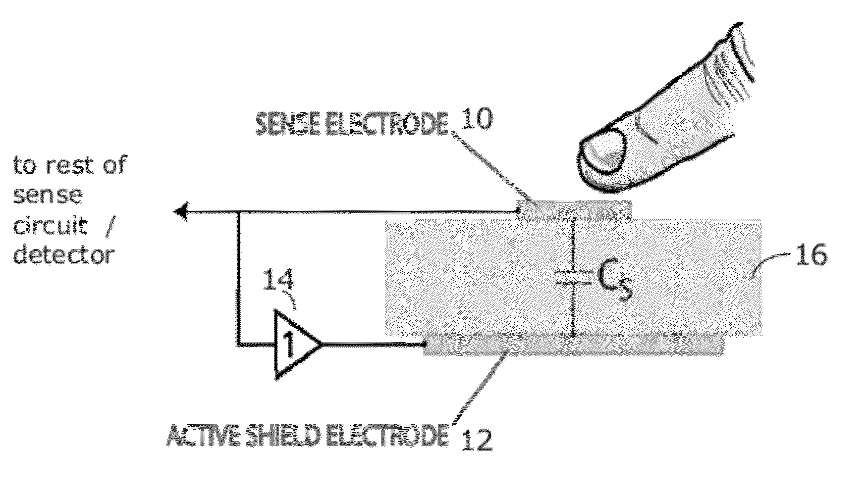
[0031]As shown in FIG. 5, parasitic capacitance of a capacitive sense electrode 10 may be effectively reduced by using an active shield electrode 12. The active shield electrode 12 is placed on a substrate, such as a printed circuit board (PCB). The active shield 12 is aligned with the sense electrode 10 on a backside (e.g., a side opposite the sense electrode 10). The active shield electrode 12 is driven with a (preferably) unity gain amplifier 14 to maintain constant DC potential difference between the shield 12 and sense 10 electrodes. As a result, the charge on the sense-to-shield capacitance CS will be unchanged, even as the sensing cir...


PUM


Abstract

A capacitive sensor having an active shield electrode driven by a unity gain amplifier. Various arrangements using multiplexors or switch arrays may allow single shield with multiple sense electrodes.

Description

RELATED APPLICATION[0001]This application claims the benefit of U.S. Provisional Application No. 61 / 387,771, filed on Sep. 29, 2010. The entire teachings of the above application(s) are incorporated herein by reference.INTRODUCTION[0002]Capacitive touch sensors are replacing switches, buttons, and knobs in new consumer electronics applications. The most famous is perhaps the circular dial on the Apple® iPod, but capacitive sense inputs are now common even on more mundane products, such as household appliances. Advantages of these touch inputs include reliability (no moving parts), lower manufacturing costs, operation in wet or dusty environments, and stylish design.[0003]Integrated circuit makers have introduced products to support capacitive touch sensors. A company called Microchip Technology, Inc. touts the “mTouch” capabilities of their microcontrollers, and Cypress Semiconductor Corporation's “PSoC Programmable System-on-Chip” products support “CapSense” inputs. These companies...

Claims


Application Information

Patent Timeline
Patent Type & Authority Applications(United States)
IPC IPC(8): G01R27/26
CPCG06F2203/04107G06F3/044G06F3/0443H03K17/962H03K2217/960765
Inventor HERRMANN, FREDERICK P.
Owner KOPIN CORPORATION
Why Eureka
Try Eureka