Charge control circuit, battery pack, and charging system

Inactive Publication Date: 2012-04-12
PANASONIC CORP
View PDF6 Cites 47 Cited by
  • Summary
  • Abstract
  • Description
  • Claims
  • Application Information

AI Technical Summary

Benefits of technology

[0008]An object of the present invention is to provide a charge control circuit, which is capable of preventing the degradation of a secondary battery more effectively than the pulse charging system and redu

Problems solved by technology

In the pulse charging system described above, however, a terminal voltage of the secondary battery exceeds the full charge voltage as soon as a charging pulse is applied to the nearly

Method used


Image

  • Charge control circuit, battery pack, and charging system
  • Charge control circuit, battery pack, and charging system
  • Charge control circuit, battery pack, and charging system

Examples


Example

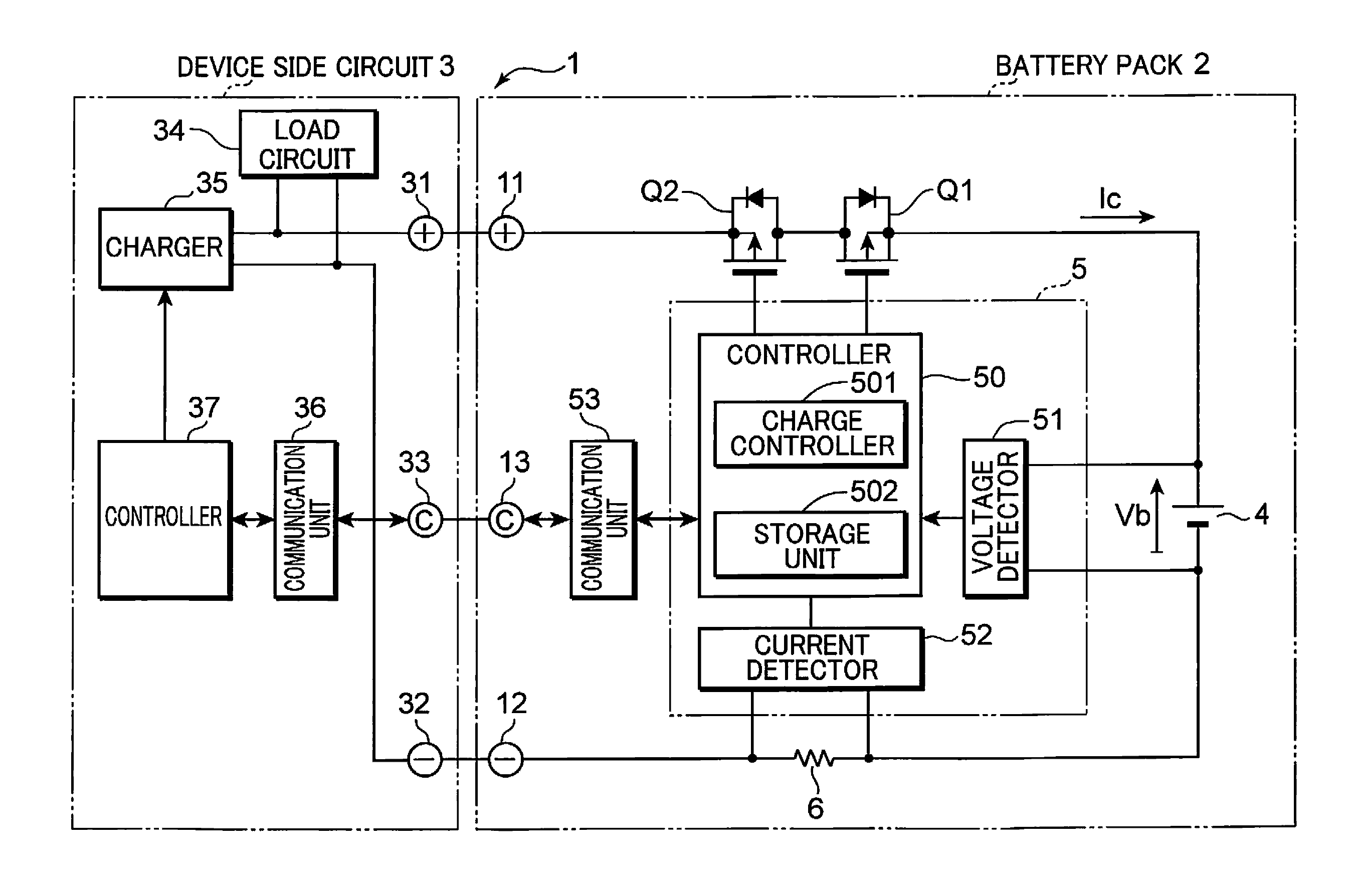
[0015]Embodiments of the present invention are described hereinafter with reference to the drawings. Note that the components shown in the diagrams are denoted with the same reference numerals to indicate the same components, and, thus, the descriptions thereof are omitted. FIG. 1 is a block diagram showing an example of configurations of a battery pack 2 and charging system 1 that have a charge control circuit 5 according to an embodiment of the present invention. The charging system 1 shown in FIG. 1 is constituted by a combination of the battery pack 2 and a device side circuit 3.

[0016]The charging system 1 is a battery-equipped device system, such as a portable personal computer, digital camera, a mobile phone and other electronic devices, or a vehicle such as an electric vehicle and hybrid car. The device side circuit 3 constitutes, for example, a main part of the battery-equipped device system, and a load circuit 34 is operated by supply of electric power from the battery pack...


PUM


Abstract

A charge control circuit includes: a charge controller for controlling an operation of a charger that charges a secondary battery; a voltage detector for detecting a terminal voltage of the secondary battery; and a current detector for detecting a current flowing to the secondary battery, wherein the charge controller repeats a plurality of times constant current constant voltage charge in which the charge controller supplies a charging current of a predetermined set current value from the charger to the secondary battery to cause the charger to execute constant current charge, and, when the terminal voltage detected by the voltage detector becomes equal to a predetermined threshold voltage value during the execution of the constant current charge, causes the charger to execute constant voltage charge by supplying a charging voltage of the threshold voltage value from the charger to the secondary battery until a current value detected by the current detector becomes equal to a predetermined threshold current value, and increases the threshold voltage value and reduces the set current value and the threshold current value each time the constant current constant voltage charge is repeated.

Description

TECHNICAL FIELD[0001]The present invention relates to a charge control circuit for controlling charging of a secondary battery, as well as to a battery pack and a charging system that have this charge control circuit.BACKGROUND ART[0002]There has conventionally been known a pulse charging system for charging a secondary battery for a short period of time with an application of a pulsed constant current (see, for example, Patent Document 1). Such pulse charging system is so designed as to reduce the charging time for a secondary battery by charging the secondary battery at a charging voltage above a full charge voltage and with a large current in a short period of time during which the pulsed current flows.[0003]There has been also known a multi-stage constant current charging system that gradually reduces the level of a charging current for constant current charge with multiple stages (see, for example, Patent Document 2). This multi-stage constant current charging system requires l...

Claims


Application Information

Patent Timeline
IPC IPC(8): H02J7/04
CPCH02J7/008H02J7/007182H02J7/00714
Inventor MAEAGAWA, KAZUYA
Owner PANASONIC CORP
Why Eureka
Try Eureka