Low leakage dynamic bi-directional body-snatching (lldbbs) scheme for high speed analog switches

a high-speed analog switch and low-leakage dynamic technology, applied in electronic switching, pulse technique, electric devices, etc., can solve the problems of high resistance, low capacitance, and small devices with higher drain to source resistan

Active Publication Date: 2012-04-12
ALPHA & OMEGA SEMICON CAYMAN
View PDF7 Cites 33 Cited by
  • Summary
  • Abstract
  • Description
  • Claims
  • Application Information

AI Technical Summary

Problems solved by technology

However, this results in high resistance because two switches are in series and have high capacitance.
However, the applications for these switches often require fast signal frequency, which means that the capacitance should be low.
However, smaller devices tend to have higher drain to source resistance in the ON state Rdson.
This is highly undesired because it results in loss of control of the MOSFET, and can cause latch up.
Furthermore, if the MOSFET M1 on-resistance Rdson is too low, then there is insufficient gate bias voltage to snatch the body.

Method used


Image

  • Low leakage dynamic bi-directional body-snatching (lldbbs) scheme for high speed analog switches
  • Low leakage dynamic bi-directional body-snatching (lldbbs) scheme for high speed analog switches
  • Low leakage dynamic bi-directional body-snatching (lldbbs) scheme for high speed analog switches

Examples


Embodiment Construction

[0023]Although the following detailed description contains many specific details for the purposes of illustration, anyone of ordinary skill in the art will appreciate that many variations and alterations to the following details are within the scope of the invention. Accordingly, the exemplary embodiments of the invention described below are set forth without any loss of generality to, and without imposing limitations upon, the claimed invention.

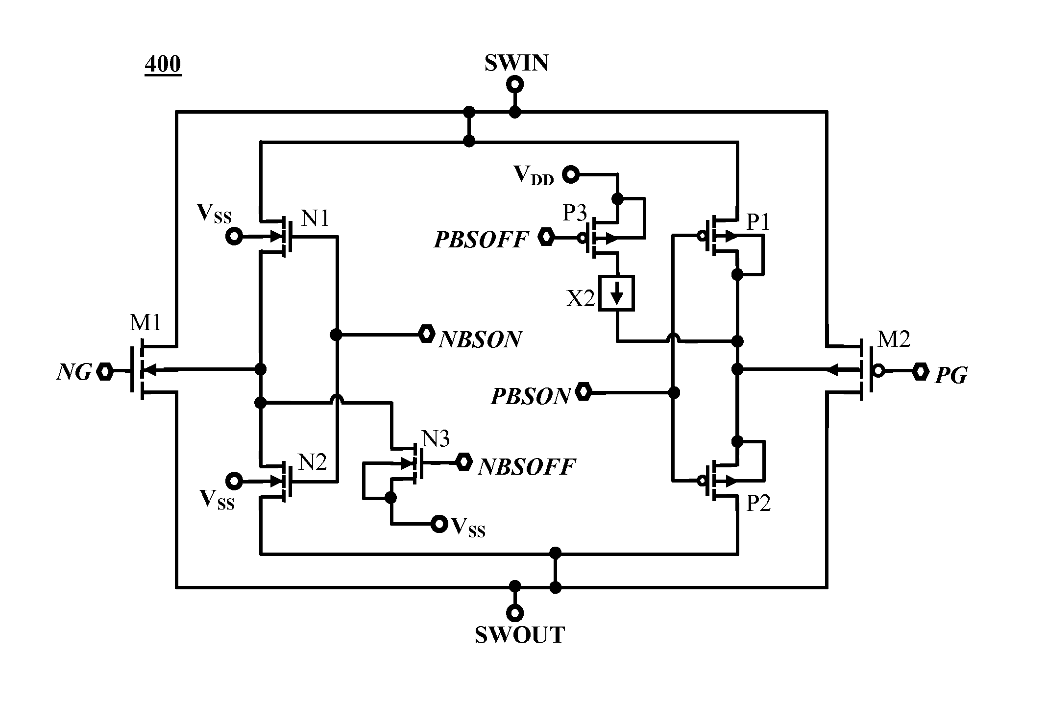
[0024]Dynamic body snatching is applied in a conventional high speed bi-directional analog switch to achieve low Rds, low quiescent currents and low power off leakage current. High speed bi-directional analog switches are used in applications for multiplex (Mux), demultiplex (De-Mux) or Universal Serial Bus (USB) (e.g., port sharing, isolation and signal Mux). A high speed bi-directional analog switch has body diodes connected to their sources when it is “ON”. As mentioned above, a high speed bi-directional analog switch, for example, an USB...


PUM


Abstract

A bidirectional switch device includes a main pass field effect transistor (FET) connected to an input node and an output node. A body region of the first main pass transistor is tied to a voltage substantially halfway between the voltage at the input node side of the first main pass transistor and the voltage at the output node side of the transistor when the first main pass transistor is in an ON state.

Description

CLAIM OF FOREIGN PRIORITY[0001]This application claims priority under 35 USC §119 to application 2425 / DEL / 2010, filed in India on Oct. 12, 2010, the entire contents of which are incorporated herein by reference.FIELD OF THE INVENTION[0002]Embodiments of the present invention are directed to high speed bi-directional analog switching and more specifically to bi-directional body snatching switches.BACKGROUND OF THE INVENTION[0003]An analog switch is used to alternately pass or block a voltage signal which is allowed to vary with time. The switching element can be a transistor, e.g., a field effect transistor (FET) such as a metal-oxide-semiconductor field-effect transistor (MOSFET). The control input to the switch is typically a standard complementary metal-oxide-semiconductor (CMOS) or transistor-transistor logic (TTL) input, which is shifted by internal circuitry to a suitable voltage for changing the state of the switch from a non-conducting state to a conducting state or vice vers...

Claims


Application Information

Patent Timeline
Patent Type & Authority Applications(United States)
IPC IPC(8): H03K17/687
CPCH03K17/145H03K2217/0054H03K2217/0036
Inventor HUSAIN, MOHAMMAD SUHAIBMALLIKARJUNASWAMY, SHEKAR
Owner ALPHA & OMEGA SEMICON CAYMAN
Why Eureka
Try Eureka