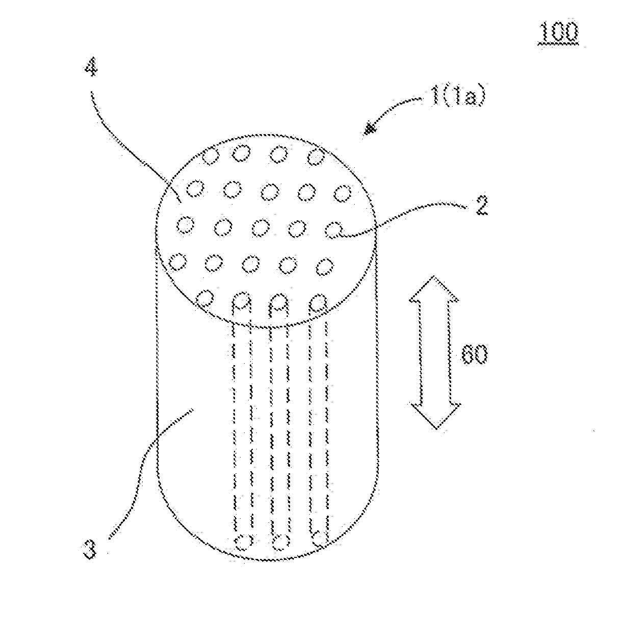
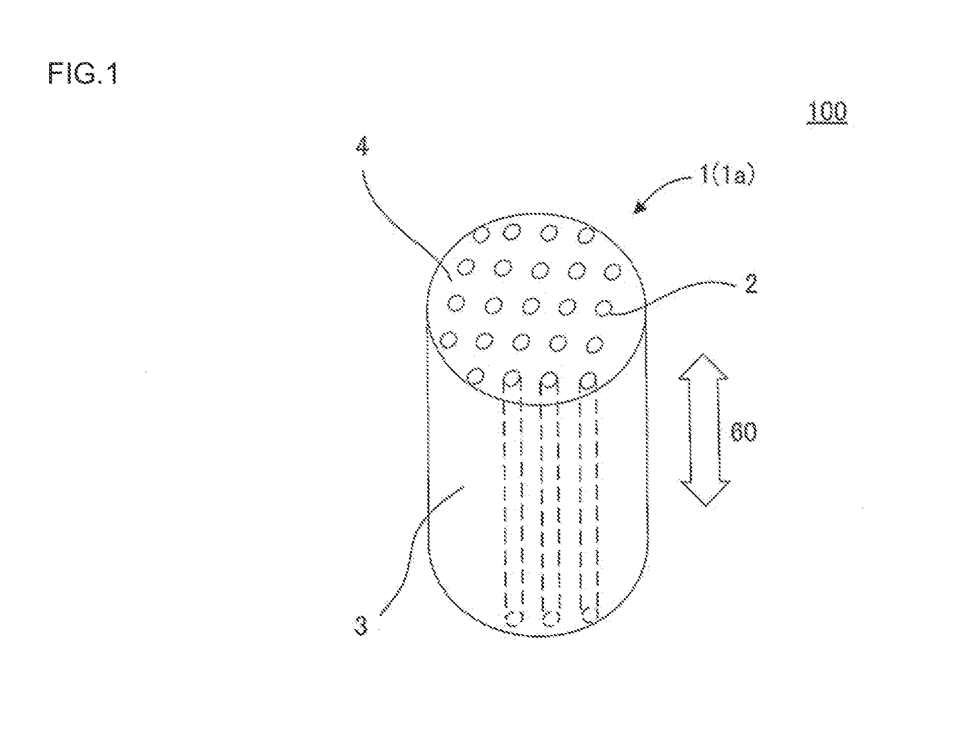
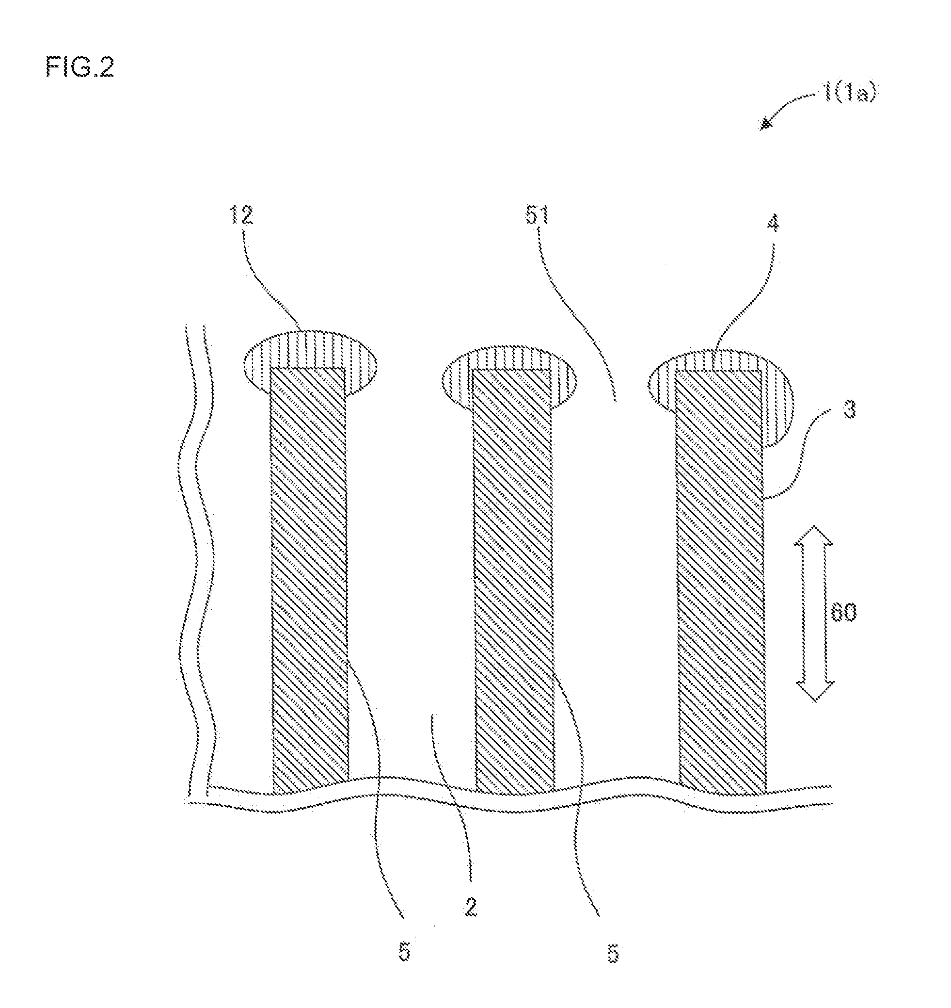
Method for producing carbon film, carbon film and separator
- Summary
- Abstract
- Description
- Claims
- Application Information
AI Technical Summary
Benefits of technology
Problems solved by technology
Method used
Image

Examples
examples 1 , 11
Examples 1, 11, Comparative Examples 1, 2
[0092]In the cases that the oxidizing gas was air (Example 1) and CO2 (Example 11), the ethanol permeation flux was raised to about 2.6 times and 1.1 times, respectively, in comparison with the carbon membrane not subjected to the heating oxidation treatment (Comparative Example 1). On the other hand, in the case that the oxidizing gas was N2 (Comparative Example 2), the permeation flux of the ethanol and the composition of the permeated liquid were about the same as those of the carbon membrane not subjected to the heating oxidation treatment (Comparative Example 1).
(3) Effect of Heating Oxidation Temperature and Time
examples 2 , 3 , 4
Examples 2, 3, 4, Comparative Example 1, 3
[0093]In the cases of Example 2 (temperature of 300° C., time of 1 hour, and A=9), Example 3 (temperature of 400° C., time of 2 hours, and A=32), and Example 4 (temperature of 250° C., time of 1 hour, A=6.3), the ethanol permeation flux was raised to about 1.4 times, 3.6 times, and 1.1 times, respectively, in comparison with the carbon membrane not subjected to the heating oxidation treatment (Comparative Example 1). On the other hand, in the case of Comparative Example 3 (temperature of 450° C., time of 2 hours, A=40.5), ethanol was not separated. In Comparative Example 3, it is assumed that the carbon membrane disappeared by excessive oxidation by an excessive treatment because time was too long with respect to temperature.
(4) Ratio (R) of Oxidizing Gas Supply Flow Rate to Membrane Area
example 7 to 9
, Comparative Example 4 to 6
[0096]Also, regarding each of the liquid mixtures of methanol and cyclohexane (Example 7, Comparative Example 4), methanol and methyl tert-butyl ether (MTBE) (Example 8, Comparative Example 5), and ethanol and cyclohexane (Example 9, Comparative Example 6), a carbon membrane subjected to a heating oxidation treatment exhibited high methanol or ethanol permeation flux in comparison with a carbon membrane not subjected to a heating oxidation treatment while separating methanol or ethanol.
(6) Other Precursors
PUM
| Property | Measurement | Unit |
|---|---|---|
| Time | aaaaa | aaaaa |
| Speed | aaaaa | aaaaa |
| Temperature | aaaaa | aaaaa |
Abstract
Description
Claims
Application Information
 - Generate Ideas
- Intellectual Property
- Life Sciences
- Materials
- Tech Scout
- Unparalleled Data Quality
- Higher Quality Content
- 60% Fewer Hallucinations
Browse by: Latest US Patents, China's latest patents, Technical Efficacy Thesaurus, Application Domain, Technology Topic, Popular Technical Reports.
© 2025 PatSnap. All rights reserved.Legal|Privacy policy|Modern Slavery Act Transparency Statement|Sitemap|About US| Contact US: help@patsnap.com