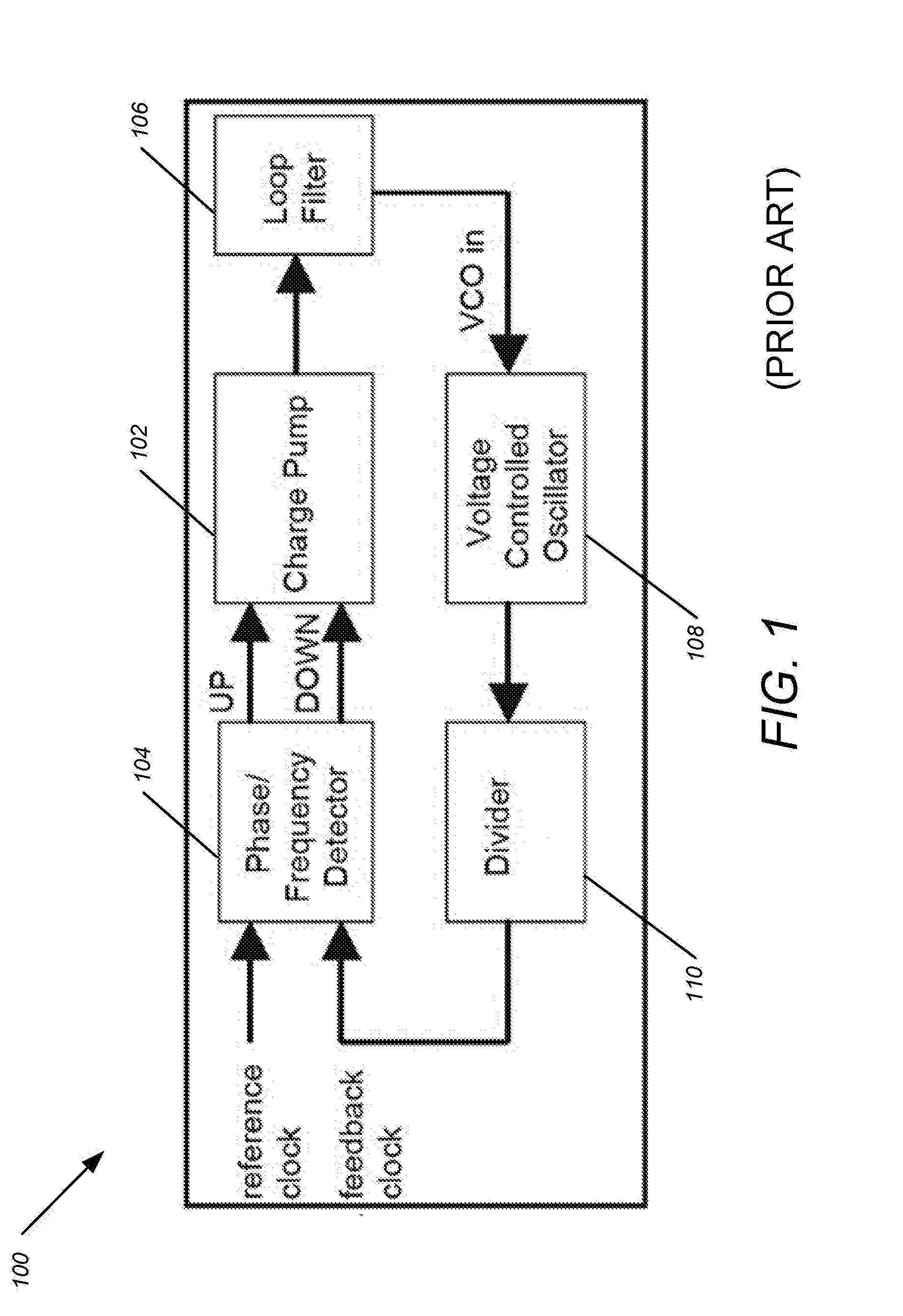
Prior art PLL charge pumps constantly consume current in the bias circuitry.
A tiny
phase error results in an indefinite charge accumulation on the
loop filter 106 if phase lock is not sufficiently precise, resulting in
phase jitter induced on the VCO 108, which is an undesirable condition.
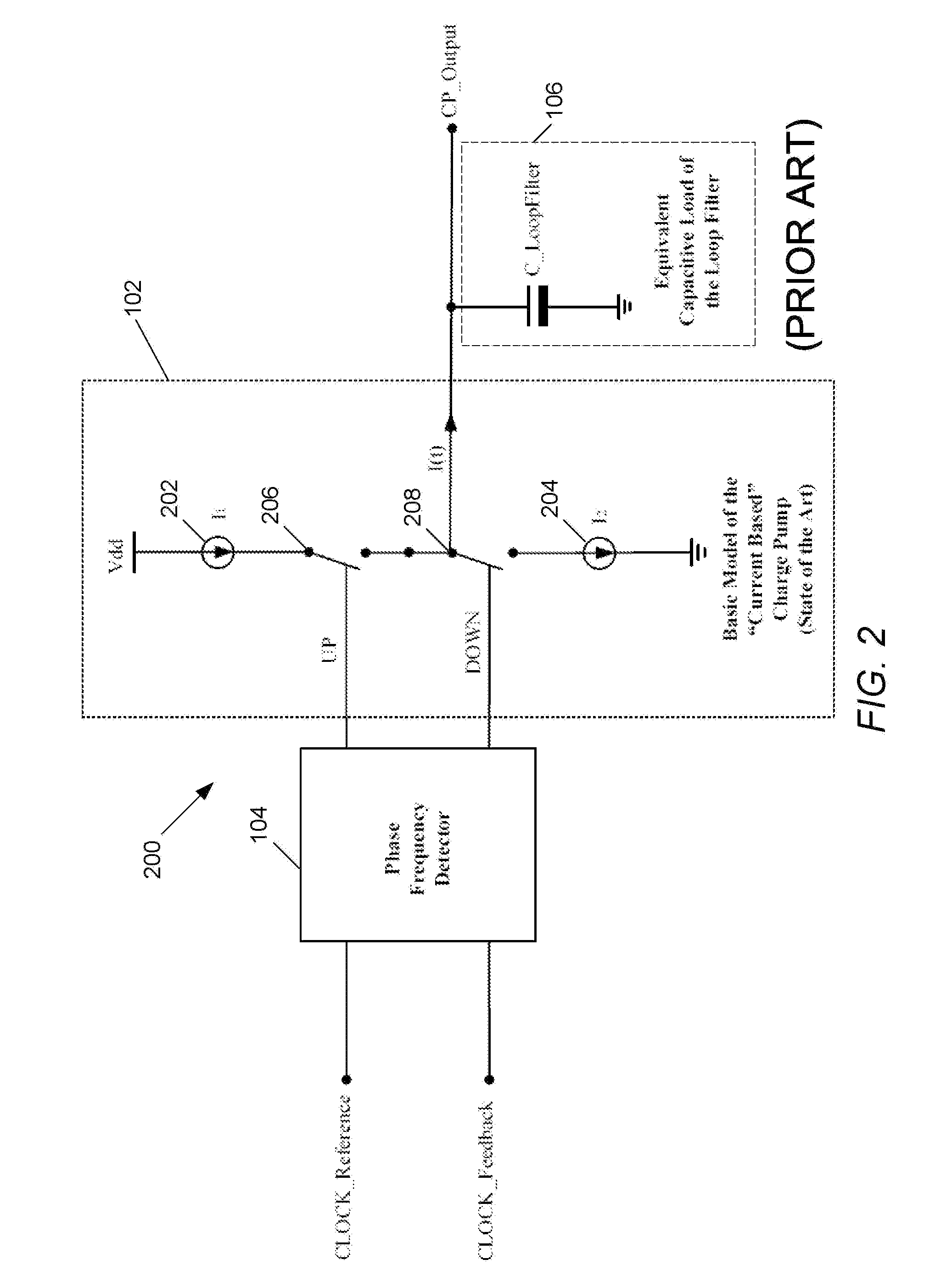
Since prior art charge pumps, e.g., as shown in FIG. 2, are current-based devices, the effect of mismatch between I1 and I2 leads to reference spurs, which are undesirable.
Unfortunately, in practice, I1 and I2 are not 100% equal due to
process variation, mismatch in the transistors and current mirrors, imperfect switches, and timing of the inputs.
A significant problem with such current-based devices is that the net charge into / from the charge pump 102 is not zero, causing an error voltage ΔV across the
loop filter 106.
This
asymmetry of charge vs.
discharge can be accommodated by the
loop filter 106, but the modulation of control voltage also creates unwanted sidebands at the PLL output, which is an undesirable condition.
These
sideband (or spurs) can create a problem in both receivers and transmitters by causing
noise.
Other common drawbacks or disadvantages of current-based PLL charge pumps include the following:
High
power consumption (e.g., ˜0.5 mW to 1 mW with a supply voltage of 1.8 V in the prior art) due to the current mirrors (several currents going up and down to bias the charge pump).
Current mirrors are not easily switched on and off quickly and tend to take a long period of time to stabilize.
For prior art PLL charge pumps it can be difficult to switch current sources on and off for short periods of time, as is required for establishing a clean voltage for locked conditions.
A drop in this at turn on and a spike at turn off produces transient errors in the output current.
Since the gate-to-source voltage on the current mirrors controls their output current, it is not a good idea to have the switch in series with the gate-to-source connection of the mirror
transistor (i.e., stacking the mirror on top of the switch).
This can result in extra complexity and reduce robustness.
Another problem of prior art current-based PLL charge pumps can be that if there is any current flowing in the power supply wires that connect the current mirrors together, a voltage between the mirror transistors is established, which modulates the charge pump output current.
Therefore, there are a lot of ways to pick up
noise in current mirrors.
A further drawback of prior art current-based PLL charge pumps is that the mirror transistors are large and take up significant area on an
integrated circuit.
As feature sizes get smaller, current sources lose manufacturing
repeatability (precision) thus matching
current mirror transistors (which are typically large) becomes more difficult.
Additionally, such current-based charge pumps of the prior art typically have exhibited a large amount of
noise near the
equilibrium point (e.g., in phase lock); this can introduce noise on the control voltage output, which must be filtered in the loop filter to keep a stable VCO frequency and phase.
Such noise is usually undesirable.
Since this
dead time error band can be approached from either UP or DOWN direction, it can be the limiting accuracy of phase lock.
For instance, such a time can result in one degree of
phase error for every 100 ps of non-overlap time (using a 36 ns clocking period or 28 MHz).
Comparatively, the prior art
current mirror charge pump requires typically around 1 to 5 ns to switch, resulting in a dithering around the target voltage so that about 20 degrees of
phase noise is generated that the loop filter is used to smooth out.
The difference between the NMOS and PMOS charges is an error added to the load
capacitance of the loop filter.
This scheme may, however, have a very small
dead band, e.g., around a degree of phase lock difference.
The downside is that a constant small step takes a longer time to lock due to the smaller transfer of charge to / from C_LoopFilter.
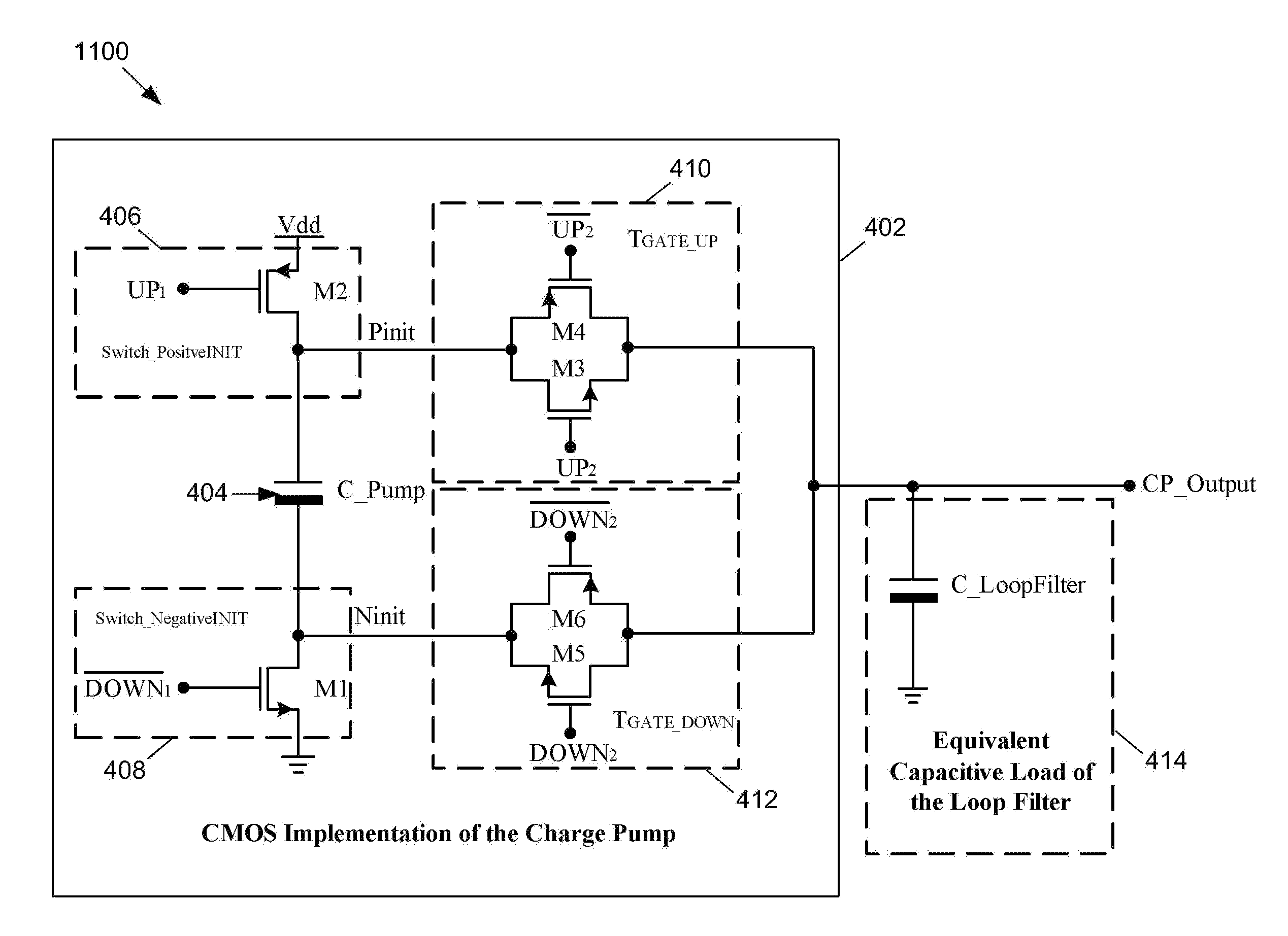
Therefore, reducing the power in the phase locked loop by use of charge-based charge pumps of the subject technology can have a pronounced
impact on the
power consumption of many overall systems, particularly battery powered devices.
In contrast, prior art charge pumps are analog devices which consume larger amounts of power,
chip area, and are subject to parametric variations that greatly affect performance.

