Burner using plasma

a technology of burners and plasma, applied in the direction of incinerators, lighting and heating apparatus, combustion types, etc., can solve the problems of industrial waste oil, high economic burden for users, and fuel burning

Inactive Publication Date: 2012-04-26
JOO SUNG HO
View PDF57 Cites 27 Cited by
  • Summary
  • Abstract
  • Description
  • Claims
  • Application Information

AI Technical Summary

Benefits of technology

[0010]As described above, the burner using plasma according to the present invention is characterized in that a combustion tank 1 configured in such a way that a mixture fuel supply pipe 3 is wound in a coil shape on an outer surface of a combustion tank 1, is designated as a positive electrode part 7, and a rod engaged at an outer side of the same is designated as a negative electrode part 8, so a direct current electricity is supplied from a direct current electricity supply part 6, and a steam supply pipe 13 serving to receive steam from the steam generation part 12 is disposed between the combustion tank 1 and the negative electrode part 8, thus forming a plasma torch part 9, so a flame of a high temperature steam plasma torch is generated in the combustion chamber 11 of the combustion tank 1. In the mode of the activation, a high temperature plasma flame can be generated at a high temperature of above 800° C., and

Problems solved by technology

The oil burner generally used at a boiler or the something is designed to use a relatively expensive fuel oil and to spray via a nozzle in a mist form, thus combusting the fuel; however the maintenance of the boiler is costly which leads to a higher economic burden to a user.
To overcome the above problems, an industrial water oil is being suggested as a fuel; however the production of the industrial waste oil is very limited, thus limiting its actual application.
Since diverse contaminations are contained in the waste oil, without a high temperature combustion, a harmful gas generated during an incomplete combustion could contaminate air.
When it is needed to properly process such harmful gas, a high temperature heat decomposition process is needed at each step, and the industrial waste oil is needed to be processed in a mixing chamber which decomposes the oil into O2, H and OH-group, and the serious contamination substances contained in the waste oil can be stabilized using hydrogen fluoride, hydrogen chloride, CO2, etc; however the decomposition process system of such serious contamination substanc

Method used


Image

  • Burner using plasma
  • Burner using plasma
  • Burner using plasma

Examples


Embodiment Construction

[0017]The preferred embodiments of the present invention will be described with reference to the accompanying drawings.

[0018]It is noted that the same reference numerals are assumed to indicate the same elements or parts. During the descriptions of the present invention, the related known functions or constructions are omitted not to make the gist of the preset invention indefinite.

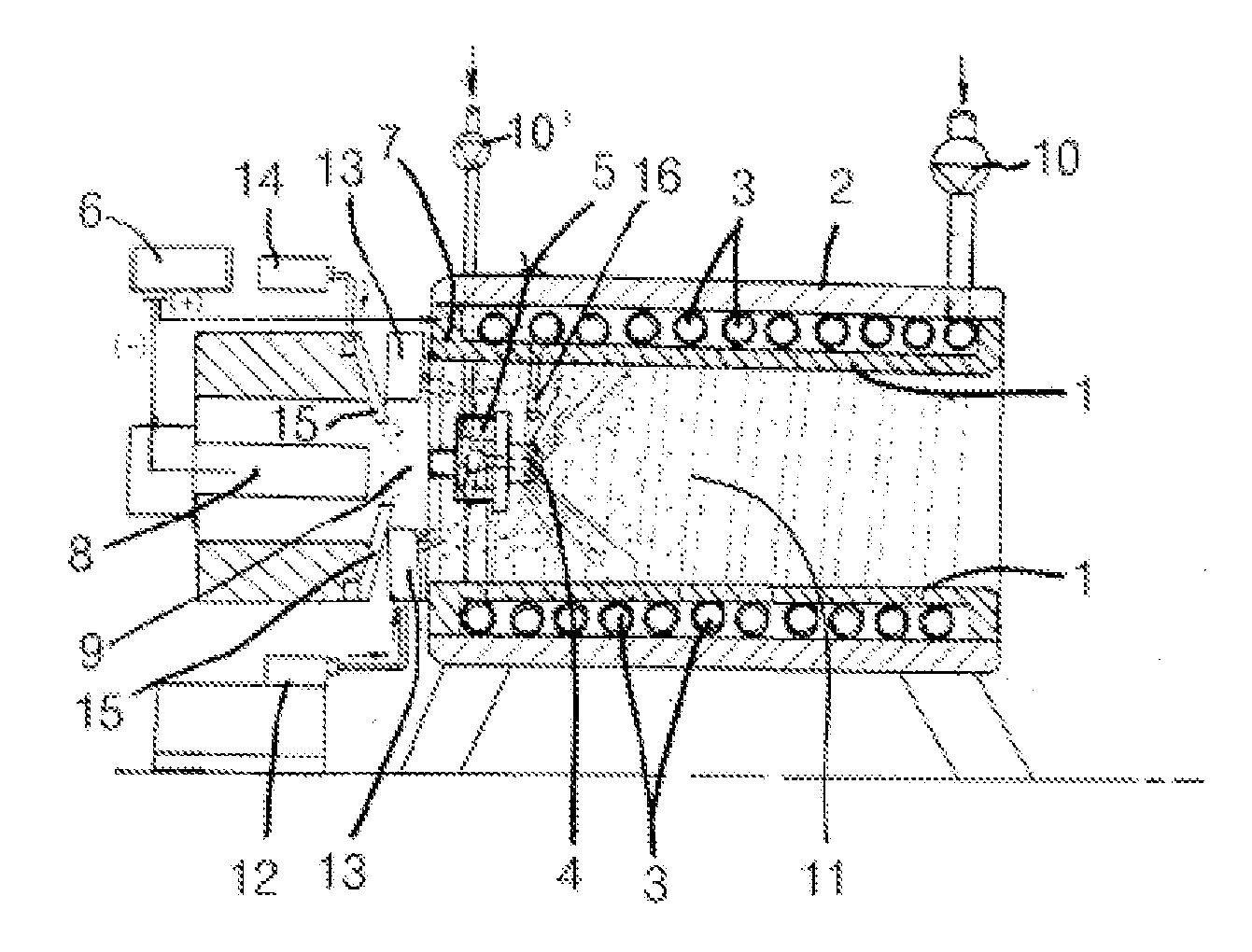
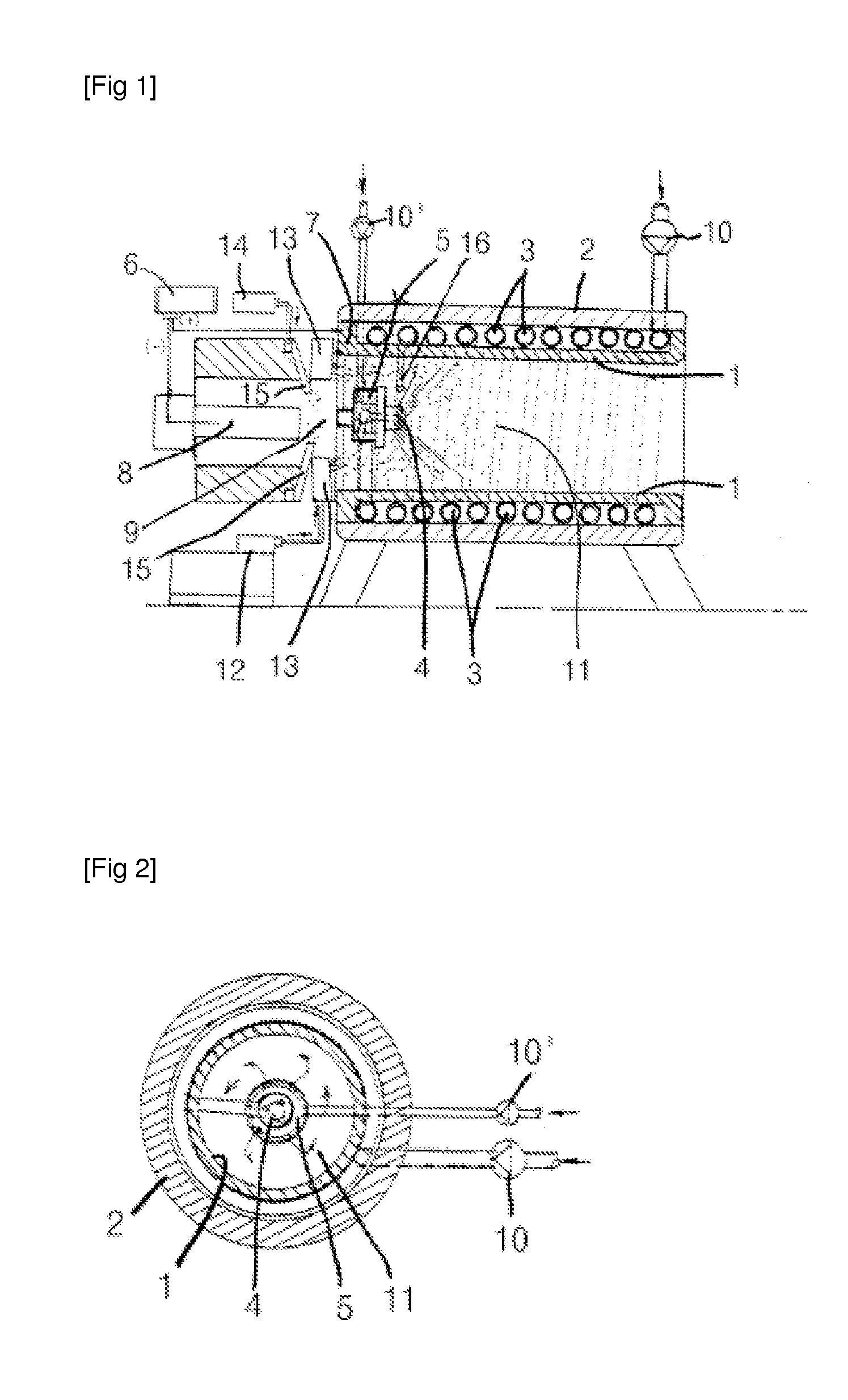
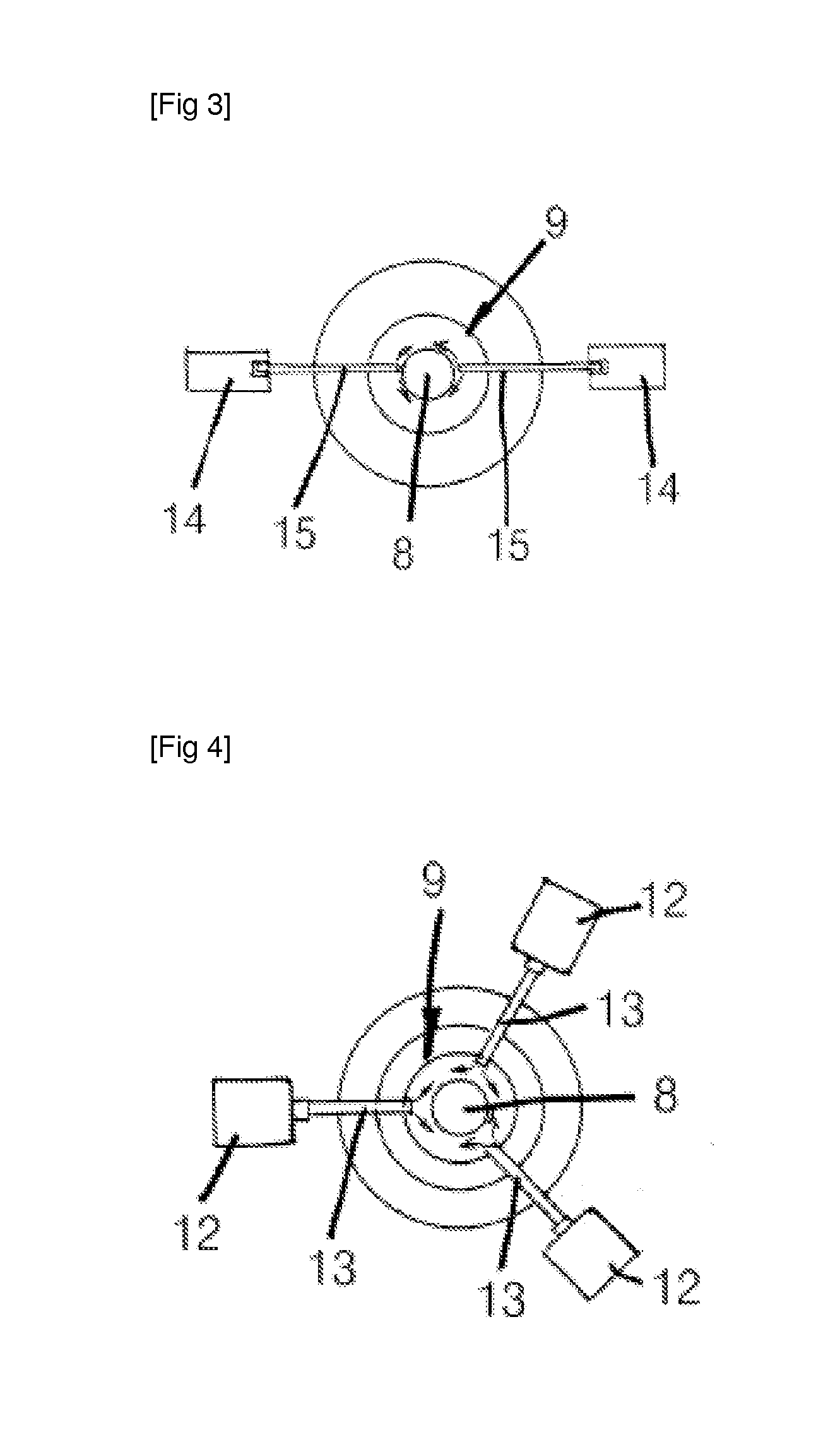
[0019]FIG. 1 is a cross sectional view illustrating the entire construction of a burner using plasma according to the present invention, FIG. 2 is a cross sectional view illustrating a combustion tank according to the present invention, FIG. 3 is a side view illustrating parts of an argon gas exhaust pipe and a negative electrode part according to the present invention, and FIG. 4 is a side view illustrating part of a steam supply pipe according to the present invention.

[0020]The present invention is characterized in that heat is collected via a combustion tank 1 formed by winding a mixture fuel supply pi...


PUM


Abstract

The present invention relates to a burner using plasma, which uses a mixture fuel in which water and industrial waste oil are mixed at an appropriate ratio. A combustion tank has a positive electrode (+), a rod installed at one side of the combustion tank has a negative electrode (−), and direct current electricity is supplied to the combustion tank and to the rod from a direct current electricity supply unit. A steam supply pipe of a steam generator is installed together with a plasma torch unit which is coupled to the combustion tank, such that high-temperature steam is discharged from the steam supply pipe together with the plasma torch generated by the plasma torch unit. Thus, the high-temperature plasma torch generates a high-temperature plasma flame of 800° C. or higher to heat a combustion chamber at the inner wall of the combustion tank. A mixture fuel supply pipe is wound into a coil on the outer surface of the combustion chamber, such that the mixture fuel supply pipe is preheated by high-temperature heat. The mixture fuel in the mixture fuel supply pipe is supplied at an air pressure of 50 through a high pressure pump, and water in the mixture fuel is decomposed into hydrogen and oxygen and waste oil in the mixture fuel is decomposed into carbons. The mixture fuel is injected or sprayed through a nozzle at a high temperature to effectively and completely burn the mixture fuel. The plasma torch unit operates by means of the direct current electricity supplied by the direct current electricity supply unit if needed, to adjust the temperature of the combustion chamber of the combustion tank, thereby enabling the smooth use of the burner.

Description

TECHNICAL FIELD[0001]The present invention relates to a burner using plasma in which a mixture fuel can be used as a combustion fuel, thus heating a boiler or the something with a cheaper fuel, with the mixture fuel being made by mixing water and industrial waste oil at a proper ratio.[0002]The present invention is basically directed to using a burner using plasma characterized in that a combustion tank helping spray a mixture fuel via a nozzle and combust the same is designated as a positive electrode (+), and a rod installed at one side of the same is designated as a negative electrode (−), thus receiving a DC (Direct Current) electricity of a DC electricity supply part, and a steam supply pipe is installed, so a mixture fuel supply pipe surrounding a combustion tank in a coil shape can be heated or preheated in such a way to heat an inner wall of the combustion tank by means of a high temperature plasma flame of above 800° C. in a combustion chamber with the aid of a flame genera...

Claims


Application Information

Patent Timeline
IPC IPC(8): F23Q7/22F23D99/00
CPCF23D11/443F23G7/05F23D11/16F23L7/005H05H1/48F23G2204/201F23D91/00F23D14/34F23D14/38
Inventor JOO, SUNG HO
Owner JOO SUNG HO
Why Eureka
Try Eureka