Thermoelectric generator including a thermoelectric module having a meandering p-n system

a technology of thermoelectric modules and generators, which is applied in the manufacture/treatment of thermoelectric devices, thermoelectric devices with peltier/seeback effects, electrical apparatus, etc., can solve the problems of reducing power plants or motor vehicles, and waste heat, so as to improve the efficiency of thermoelectric generators and reduce the weight of components. , the effect of reducing the number of heat transfers

Inactive Publication Date: 2012-05-03
ROBERT BOSCH GMBH
View PDF15 Cites 17 Cited by
  • Summary
  • Abstract
  • Description
  • Claims
  • Application Information

AI Technical Summary

Benefits of technology

[0005]With the aid of an example p-n-legs construction according to the present invention, the number of heat transfers is reduced, thereby improving the efficiency of the thermoelectric generator. Since a mechanical bracing used in the conventional stack system is omitted, the weight of the components is additionally reduced so that a weight-reduced and compact component having reduced manufacturing costs is obtained.

Problems solved by technology

Waste heat, for example from power plants or motor vehicles, is often released unused into the environment.
By putting the thermoelectric modules in stacks, additional heat transfers develop, resulting in heat losses which reduce the efficiency of the thermoelectric generator.
Moreover, if a mechanical bracing is provided, the total weight of the thermoelectric generator increases due to the bracing components.
In addition, preparing the thermoelements on the carrier foils preferably includes thin-film deposition of thermoelectric materials and metals, as well as subsequent structuring with the aid of wet chemical etching, which is associated with high expenditures in terms of time and materials during the manufacturing.

Method used


Image

  • Thermoelectric generator including a thermoelectric module having a meandering p-n system
  • Thermoelectric generator including a thermoelectric module having a meandering p-n system
  • Thermoelectric generator including a thermoelectric module having a meandering p-n system

Examples


Embodiment Construction

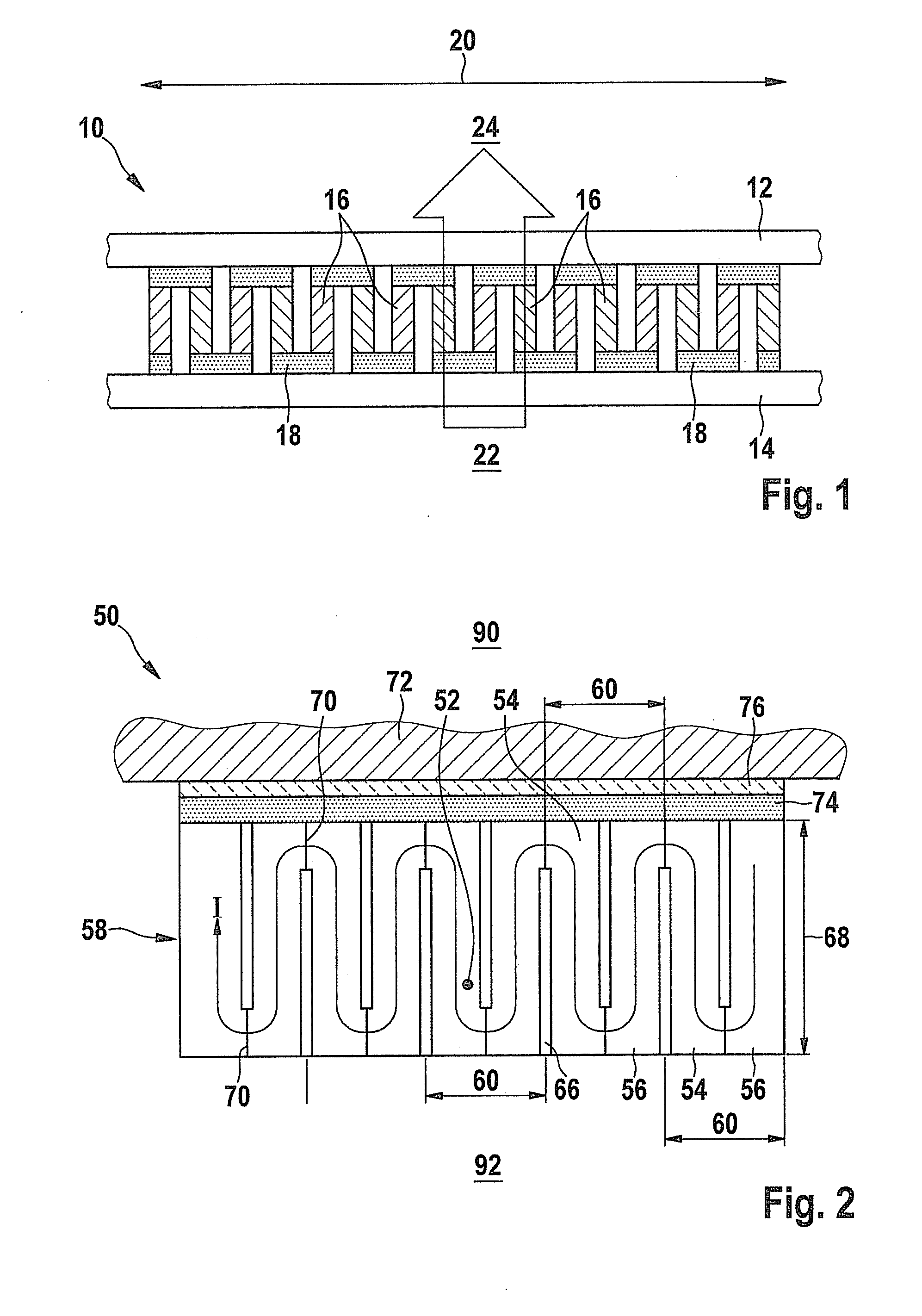
[0015]For the purpose of better explaining the present invention, FIG. 1 shows a conventional thermoelement or a conventional thermoelectric module 10.

[0016]A thermoelectric module 10 is usually composed of two thin electrically insulating plates 12, 14 between which small blocks 16 made of different material are positioned. Every two blocks 16 of different material are connected with each other via contact isles 18 in such a way that they form an electric series circuit 20. One of the two plates 12 absorbs inflowing heat flow 22 (hot side), while the other plate 14 gives off outflowing heat flow 24 (cold side). The heat flow, which flows from the hot to the cold side, flows parallel through all blocks 16.

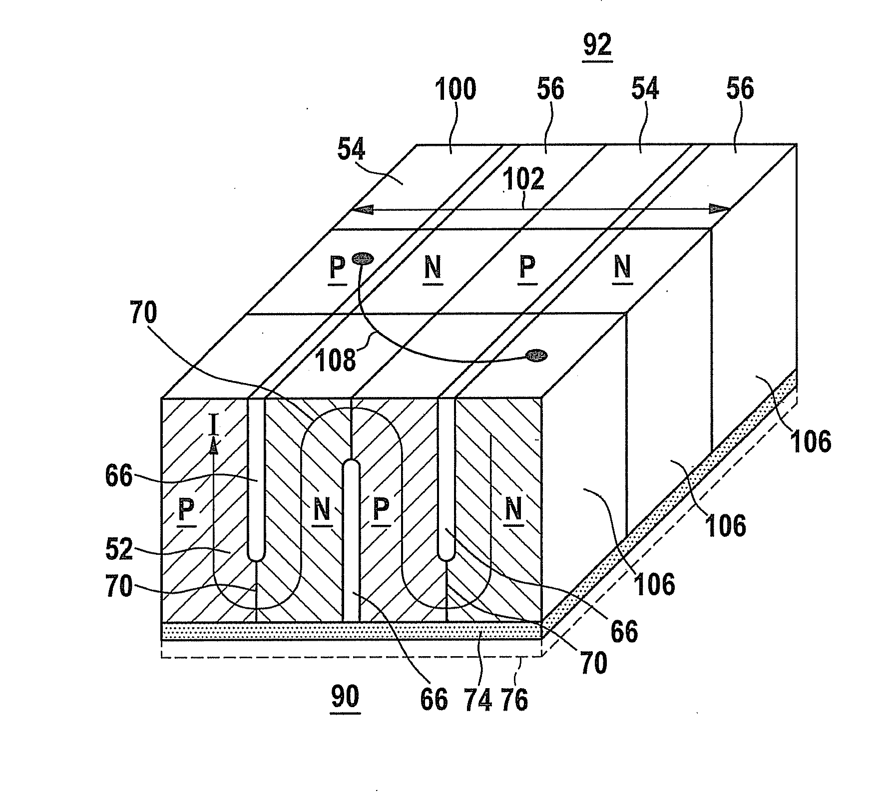
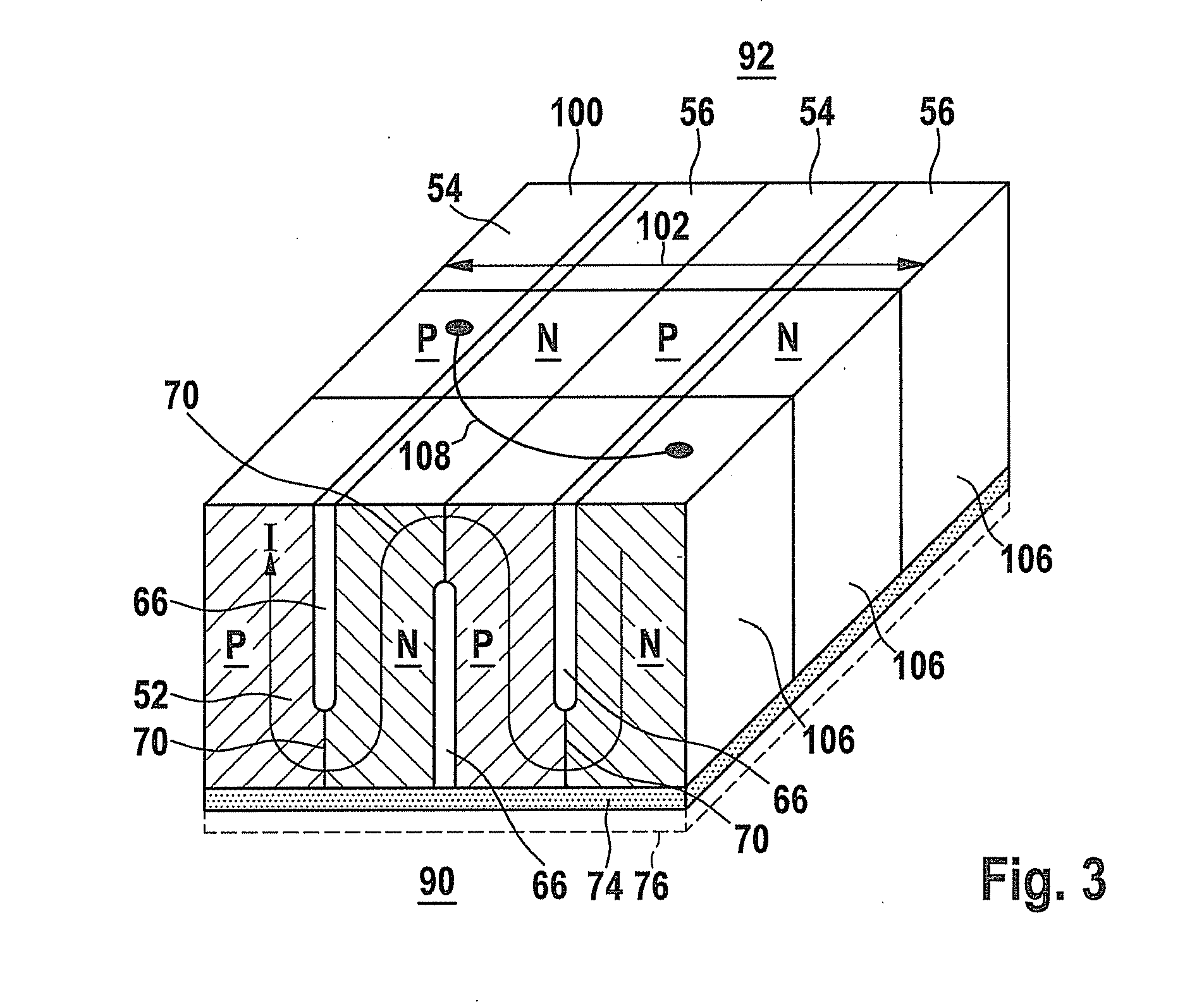
[0017]FIG. 2 shows a front view of an example thermoelectric module 50 according to the present invention having a plurality of p- and n-legs 54, 56 which are positioned in series in a block 58. One p-n-couple 60 is formed by a conductor pair made of semiconductor materials that is...


PUM


Abstract

A thermoelectric module having a plurality of p-n-couples, every two adjacent p-n-legs forming one p-n-couple. The p-n-legs are each manufactured from conductive materials. The p-n-legs of the plurality of p-n-couples are separated in an alternating sequence by an electrically insulating gap which creates a meandering current flow.

Description

CROSS REFERENCE[0001]The present application claims the benefit under 35 U.S.C. §119 of German Patent Application No. DE 102010043281.4 filed on Nov. 3, 2010, which is expressly incorporated herein by reference in its entirety.BACKGROUND INFORMATION[0002]Waste heat, for example from power plants or motor vehicles, is often released unused into the environment. Effectively utilizing this heat energy would, however, result in a higher efficiency. One possibility of utilizing this waste heat are thermoelectric generators (TEG) which, in case of a temperature difference, generate an electric voltage due to the Seebeck effect, also referred to as thermoelectric effect. Devices for generating energy from waste heat are described in German Patent Application No. DE 10 2008 005 334 A1, for example.[0003]Thermoelectric generators have been hitherto often employed in the form of a stack system. This is described in German Patent Application No. DE 10 2005 009 480 A1, for example. In this syst...

Claims


Application Information

Patent Timeline
Patent Type & Authority Applications(United States)
IPC IPC(8): H01L35/32H01L35/34
CPCH01L35/32H10N10/17
Inventor KRINN, ILONASTOECKLEIN, WOLFGANGSCHMITT, MANFREDKEMMLER, LUDWIG
Owner ROBERT BOSCH GMBH
Why Eureka
Try Eureka