Multi-junction solar cell with dilute nitride sub-cell having graded doping

Active Publication Date: 2012-05-03
ARRAY PHOTONICS INC
View PDF2 Cites 63 Cited by
  • Summary
  • Abstract
  • Description
  • Claims
  • Application Information

AI Technical Summary

Benefits of technology

[0013]Common to all of these embodiments is a significant functional relationship between overall performance and the vertical distribution of doping in the base and/or emitter of the dilute nitride sub-cells. The doping concentration may be selected so as to have positional dependence, in which dependence varies as a function of vertical position in the base or the emitter. By way of an example, the doping could be designed to increase linearly or exponentially from the top to bottom in the base. Stated in mathematical terms, the doping concentration “d” has a functional dependence such that d=F(x) (i.e., doping is a function

Problems solved by technology

It is possible that a concentrator's optics may attenuate light in a particular wavelength region which may be detrimental to the dilute nitride sub-cell.
This is particularly important if dilute nitride sub-cells are to be used because dilute nitride semiconductor materials historically have been plagued with poor minority carrier transport properties that prove detrimental when incorporated into a larger solar cell.
Although dilute nitride alloys have other properties that make them desirable for use in multi junction structures, particularly the flexibility with which their bandgaps and lattice constants can be fine-tuned as part of their design, the minority carrier lifetime and diffusion lengths for these sub-cells are typically worse than with conventional solar cell semiconductors such as GaAs and InGaP used in conventional multi junction solar cells, thus resulting in a loss of short circuit current, open circuit voltage or both.
As a result of these problems, photocurrents generated i

Method used


Image

  • Multi-junction solar cell with dilute nitride sub-cell having graded doping
  • Multi-junction solar cell with dilute nitride sub-cell having graded doping
  • Multi-junction solar cell with dilute nitride sub-cell having graded doping

Examples


Example

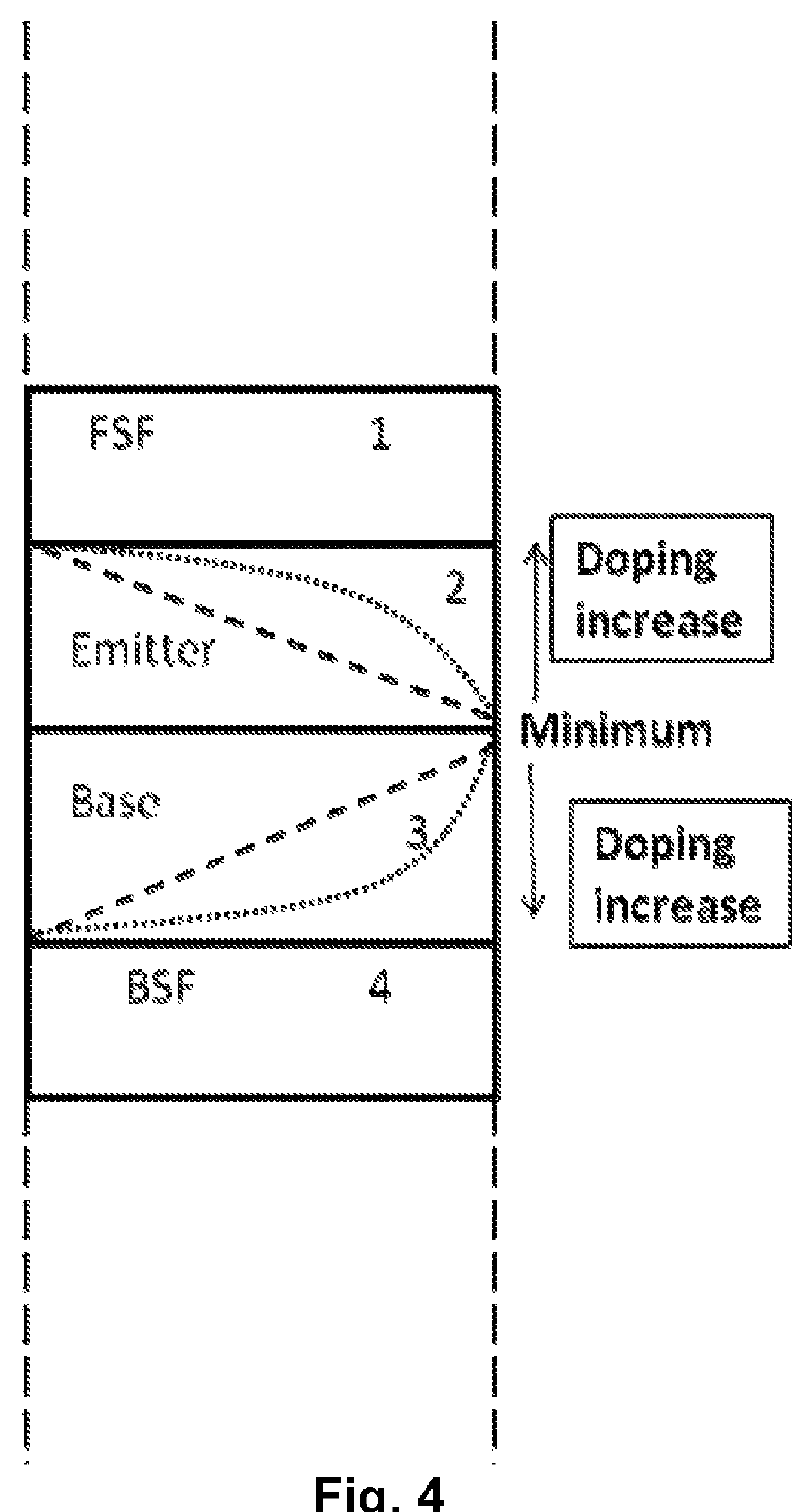
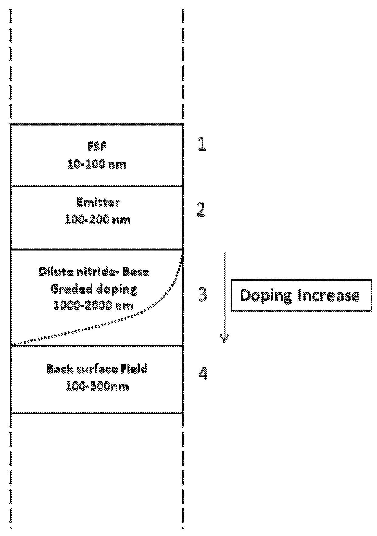
[0028]According to the invention, a multi junction solar cell includes at least a dilute nitride solar sub-cell with tailored and more specifically graded doping and / or impurity concentration, as herein described. Without limiting the generality of the invention, a multi junction solar cell having one or more dilute nitride sub-cells takes advantage of the functional dependence of sub-cell performance on the vertical distribution of doping within the base and / or emitter of the sub-cell. Graded doping indicates a functional dependence on the position in the base and / or emitter.

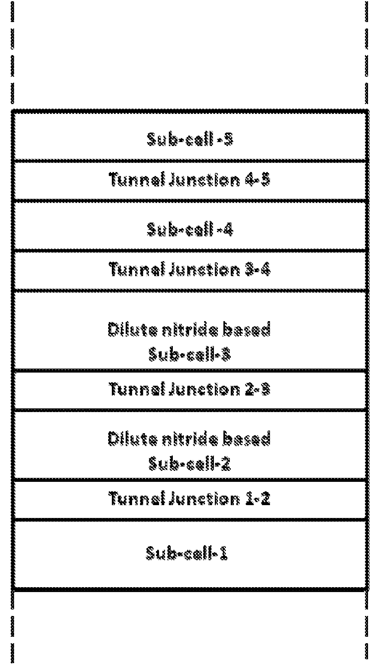
[0029]FIG. 1 shows the schematic of an exemplary triple junction solar cell with three sub-cells, of which the bottom cell is a dilute nitride sub-cell. In this embodiment, the substrate can be any conventional substrate used for epitaxy selected from the group including but not limited to GaAs, Ge, InP, GaSb and comparable materials. Above the substrate, the triple junction cell has a bottom sub-cell 1, middle...


PUM


Abstract

A lattice-matched solar cell having a dilute nitride-based sub-cell has exponential doping to thereby control current-carrying capacity of the solar cell. Specifically a solar cell with at least one dilute nitride sub-cell that has a variably doped base or emitter is disclosed. In one embodiment, a lattice matched multi junction solar cell has an upper sub-cell, a middle sub-cell and a lower dilute nitride sub-cell, the lower dilute nitride sub-cell having doping in the base and/or the emitter that is at least partially exponentially doped so as to improve its solar cell performance characteristics. In construction, the dilute nitride sub-cell may have the lowest bandgap and be lattice matched to a substrate, the middle cell typically has a higher bandgap than the dilute nitride sub-cell while it is lattice matched to the dilute nitride sub-cell. The upper sub-cell typically has the highest bandgap and is lattice matched to the adjacent sub-cell. In further embodiments, a multi junction solar cell according to the invention may comprise four, five or more sub-cells in which the one or more sub-cells may each comprise exponentially doped dilute nitride alloys.

Description

CROSS-REFERENCES TO RELATED APPLICATIONS[0001]Not ApplicableSTATEMENT AS TO RIGHTS TO INVENTIONS MADE UNDER FEDERALLY SPONSORED RESEARCH AND DEVELOPMENT[0002]Not ApplicableREFERENCE TO A “SEQUENCE LISTING,” A TABLE, OR A COMPUTER PROGRAM LISTING APPENDIX SUBMITTED ON A COMPACT DISK[0003]Not ApplicableBACKGROUND OF THE INVENTION[0004]The invention relates to solar cell design and more particularly to multi junction solar cells employing dilute nitrides.[0005]The highest solar cell efficiencies are known to be produced by multi junction (MJ) solar cells comprising III-V semiconductor alloys. Their relatively higher efficiencies make these devices attractive for both terrestrial concentrating photovoltaic systems and for celestial systems designed to operate in outer space. Multi junction solar cells have reached efficiencies up to 41.6% under concentrations equivalent to several hundred suns. Currently, the highest efficiency devices have three junctions and are either lattice matched...

Claims


Application Information

Patent Timeline
IPC IPC(8): H01L31/0288H01L31/18
CPCH01L31/03042Y02E10/544H01L31/0687H01L31/03048H01L31/065H01L31/0725H01L31/0735H01L31/1844
Inventor MISRA, PRANOBJONES, REBECCA ELIZABETHLIU, TINGFUSHMAN, ILYAYUEN, HOMAN BERNARD
Owner ARRAY PHOTONICS INC
Why Eureka
Try Eureka