
High resolution microscopy using an optically switchable fluorophore

a fluorophore and high-resolution technology, applied in the field of microscopy, can solve the problems of fast and precisely synchronized pulses, and achieve the effects of maximizing the number of fluorescent photons emitted, good time resolution, and improving resolution

Active Publication Date: 2012-05-10
BAER STEPHEN C
View PDF3 Cites 9 Cited by
  • Summary
  • Abstract
  • Description
  • Claims
  • Application Information

AI Technical Summary

Benefits of technology

The invention is a method for using a fluorescent protein called Dronpa to visualize the location of a chosen protein in a cell. The method involves expressing Dronpa in the cell as a fusion protein with another protein. The Dronpa molecules are enriched in the center of a scanned spot by selectively switching them on. This difference allows the doughnut beam to interact with a light receptive mechanism that is up to a thousand times more sensitive than the "off" switch. The ratio of emitted fluorescent photons per doughnut photon is improved by a factor of a thousand, reducing tissue toxicity, improving resolution, and shortening exposure time. The method uses a different state of the Dronpa molecule than the "off" switch, resulting in improved performance.

Problems solved by technology

However this particular intermediate state would require very fast and precisely synchronized pulses.

Method used


Image

  • High resolution microscopy using an optically switchable fluorophore
  • High resolution microscopy using an optically switchable fluorophore
  • High resolution microscopy using an optically switchable fluorophore

Examples


Embodiment Construction

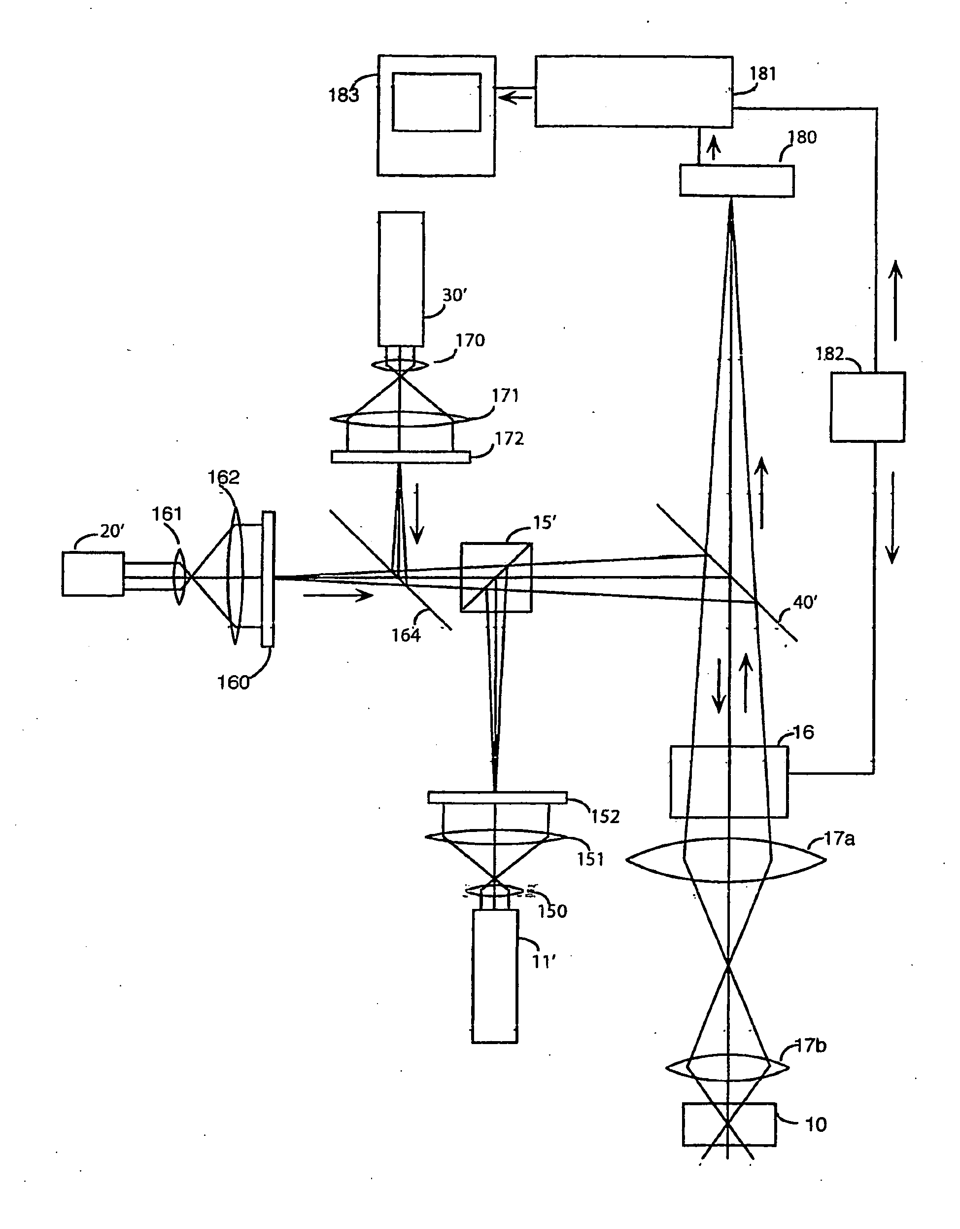
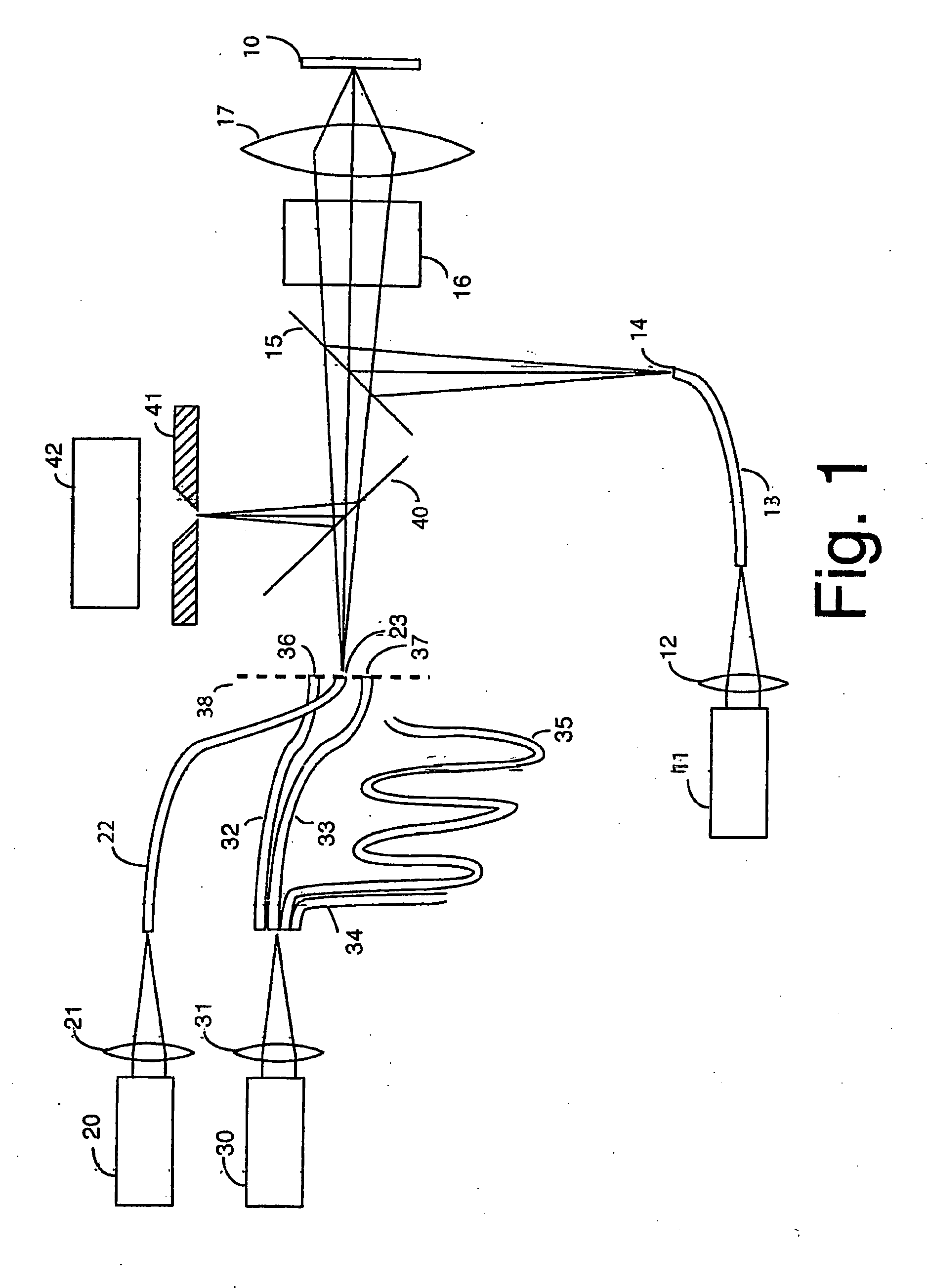
[0024]The first embodiment of the present invention to be described is a modification of a microscope described in FIG. 10 of Baer, U.S. Pat. No. 5,952,668, which is incorporated herein by reference. The specimen 10 contains cells that express the protein Dronpa in some chosen subcellular element to be visualized. The output of laser 11, at the wavelength 488 nm, effective as an “off” switch for Dronpa, is focused by lens 12 on one end of optical fiber 13, the other end 14 of which is in a real image plane, and following reflection by beam splitter 15, passage through x, y scanner device 16 and focusing by objective lens 17, the output of laser 11 is focused on a spot in specimen 10. We can imagine that the spot is initially at or near the upper left hand corner of a field to be raster scanned.

[0025]After sufficient time to thoroughly turn off the Dronpa molecules in the focused spot, laser 11 is turned off and laser 20 emits a 100 to 200 femtosecond pulse at 405 nm, a wavelength ef...


PUM

PropertyMeasurementUnit
quantum efficiencyaaaaaaaaaa
wavelengthaaaaaaaaaa

Abstract

The invention relates to a method for high resolution visualization of a compound that can be switched by a switching signal from a state of low fluorescence to a state of higher fluorescence, and then revert to the state of low fluorescence. Said switching signal is directed to a spot in a region of a material containing said compound, and an optical signal adapted to lower the probability that said switching signal will successfully switch said compound to said state of higher fluorescence is directed to said spot and shaped to have a minimum in said spot, such that the probability that said switching signal successfully switches said compound is greatest at said minimum. Said spot containing both said switching signal and said optical signal is scanned over said region of said material while monitoring the fluorescence from said compound in said spot to create an image of said region. In some embodiments of the invention a plurality of spots are simultaneously scanned, to reduce the imaging time.

Description

CROSS REFERENCE TO RELATED APPLICATION[0001]This application claims priority from U.S. Provisional Patent Application Ser. No. 60 / 715,480 filed 10 Sep. 2005, the entire disclosure of which is hereby incorporated by reference.FIELD OF THE INVENTION[0002]The present invention relates to microscopy and more particularly to methods for increasing resolution in fluorescence microscopy. Still more particularly, the invention relates to methods for resolution enhancement wherein the effective diameter of the point spread function of a scanned spot is reduced by selectively reducing fluorescence in its periphery.BACKGROUND OF THE INVENTION[0003]The present invention is in the area of optical technology in which resolution of an image forming process is improved by reshaping the point spread function of a diffraction-limited spot or line to decrease intensity in its periphery compared to its center, thereby reducing its effective diameter or width. The original examples of this point spread ...

Claims


Application Information

Patent Timeline
Patent Type & Authority Applications(United States)
IPC IPC(8): G01N21/64
CPCG02B21/0072G02B21/0076G06T2207/10064G06T5/003G06T2207/10056G06T2207/30024G06T5/73
Inventor BAER
Owner BAER STEPHEN C
Learn More