
Flexible gas barrier film, method for preparing the same, and flexible display device using the same

a gas barrier film and flexible technology, applied in the field of gas barrier films, can solve the problems of difficult to implement the substrate to be used, lower gas barrier ability of plastic substrates, and shorter lifespan, and achieve the effects of effective reducing water vapor permeability, high gas barrier ability, and no increase in production costs

Inactive Publication Date: 2012-05-10
KOREA UNIV RES & BUSINESS FOUND
View PDF0 Cites 7 Cited by
  • Summary
  • Abstract
  • Description
  • Claims
  • Application Information

AI Technical Summary

Benefits of technology

[0008]Accordingly, it is an object of the present invention to provide a flexible gas barrier film which is capable of maximizing hydrophobicity and increasing a water repulsive force by patterning a hydrophobic layer.
[0009]It is another object of the present invention to provide a flexible gas barrier film which is capable of further reducing water vapor permeability by discharging water from a hydrophobic surface to an outer hydrophilic region by forming a patterned hydrophilic layer on the patterned hydrophobic layer.
[0010]It is still another object of the present invention to provide a flexible gas barrier film which is capable of effectively reducing water vapor permeability by controlling a surface tension of existing barrier material, without increasing production costs.

Problems solved by technology

As it is not easy to implement a substrate to be used for such a flexible display using an existing rigid glass substrate, a transparent plastic substrate is being now used for the flexible display substrate.
However, while such a glass substrate can provide effective prevention of water and oxygen from permeating into the substrate, the plastic substrate has lower gas barrier ability because of it larger permeability of water and oxygen than the glass substrate.
Use of a substrate having lower gas barrier ability may contribute to shorter lifespan due to reaction with organic substance permeating into the substrate and degradation of display quality due to deterioration of elements by permeation of vapor or air into the substrate.
Unfortunately, this technique has a problem of diffusion of water into a ceramics layer or the like due to small pin holes or cracks.
However, although these disclosed gas barrier films may act to decrease a diffusion speed of water in a passivation film or enlarge a diffusion path, they have demerits of insufficient gas barrier performance due to excess of water vapor permeability over 0.1 g / m2 day and impossibility of prevention of a minute amount of water from permeating into elements with temporal variation of the films.
On the other hand, there has been proposed a method for forming a multi-layered gas barrier structure for sufficient gas barrier performance; however, this method also has a problem of poor productivity due to increased thickness of a gas barrier film and generation of cracks due to tension occurring in a barrier layer.
However, this disclosed structure also has a disadvantage in that a parylene layer has to be deposited with a thickness of 5 μm or more in order to achieve sufficient gas barrier ability.

Method used


Image

  • Flexible gas barrier film, method for preparing the same, and flexible display device using the same
  • Flexible gas barrier film, method for preparing the same, and flexible display device using the same
  • Flexible gas barrier film, method for preparing the same, and flexible display device using the same

Examples


example 1

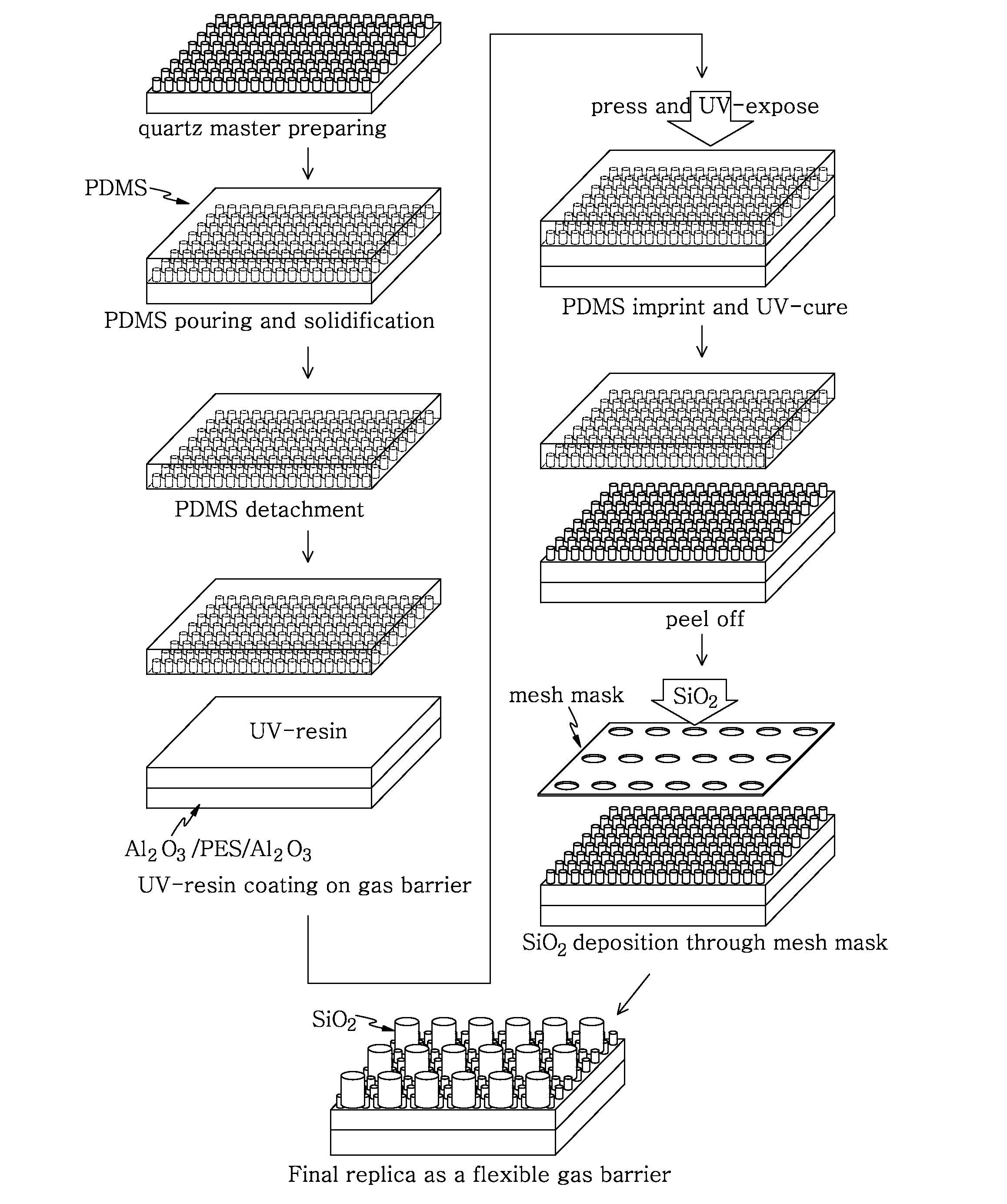
[0099]A 300 nm-thick Al2O3 (purity: 99.99%) layer was deposited as a gas barrier on a surface of a 200 μm-thick polyethersulfone (PES) substrate (glass transition temperature: 223° C., available from i-Components Ltd., Co.) using E-beam and a hydrophobic layer was formed by drop-casting Multi-cure 984-LVF (available from DYMAC Ltd., Co.) and then coating the Al2O3 layer with the coating material at a thickness of 1 μm using UV-curing. Time taken for UV-curing was one minute, equipment employed for UV-curing was CURE ZONE HO2 (available from Daeho Glue Tech Ltd., Co.), and the UV-curing was carried out under conditions of wavelength of 365 nm and power of 120 mW / cm. In this case, a surface tension of the hydrophobic layer was 25.8 mN / m, a surface contact angle of DI water was 79.8°, and a surface contact angle of Formamide was 72.8°. Thereafter, polydimethylsiloxane (PDMS) material was contacted and cured with the hydrophobic layer, exposed to ultraviolet rays, and then separated fro...

embodiment 2

[0100]In this embodiment, a flexible gas barrier film was prepared with the same process as Embodiment 1 except that a 300 nm-thick Al2O3 (purity: 99.99%) layer was deposited on both surfaces of a polyethersulfone (PES) substrate. A water vapor permeability of the prepared film was 0.00208 g / m2 day.

embodiment 3

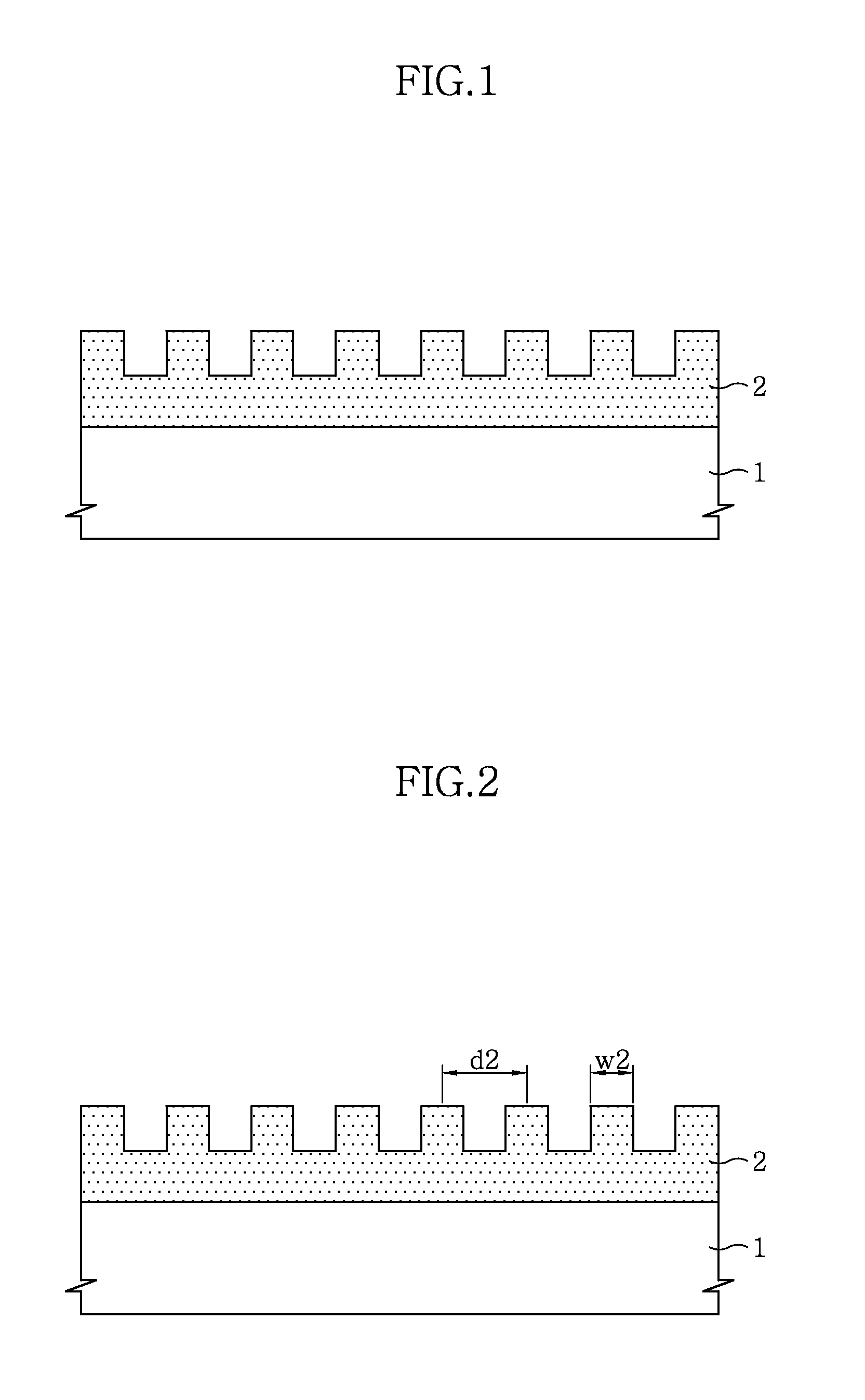
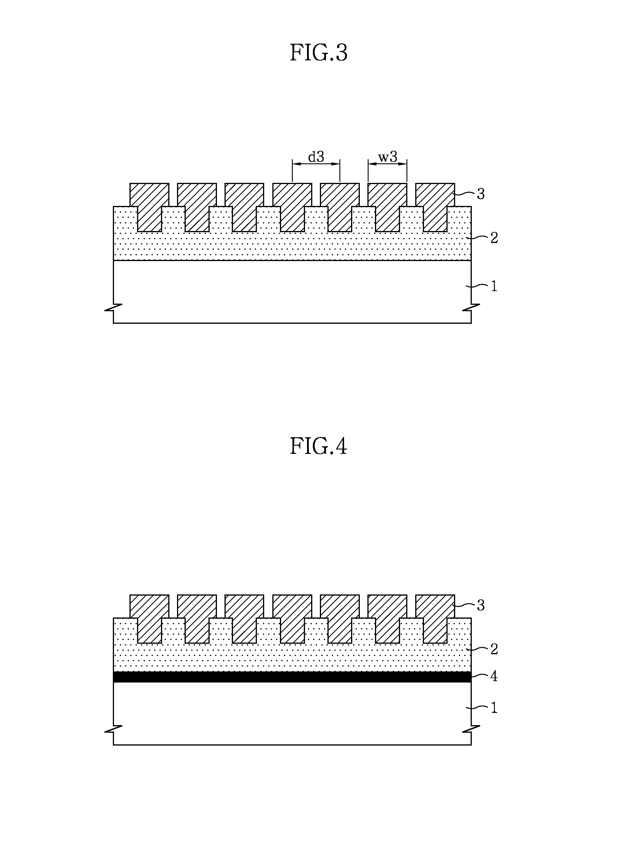
[0101]In this embodiment, a flexible gas barrier film was prepared with the same process as Embodiment 2 except that a 450 nm-thick SiO2 (purity: 99.99%) layer was deposited on the hydrophobic pattern layer by E-beam evaporation using a stainless shadow mask. In this case, size of dots was set to 0.5 mm and a distance between centers of pattern was set to 1 mm. A surface tension of a hydrophilic pattern layer was 73.12 mN / m and surface contact angles of DI water and Formamide were less than 5°. A water vapor permeability of the prepared film was 0.000534 g / m2 day. FIG. 7 shows a process of forming a hydrophilic pattern layer according to Embodiment 3 and FIG. 8 is a schematic view showing a flexible gas barrier film with a hydrophilic pattern layer formed thereon according to Embodiment 3. FIG. 10 shows comparison of water vapor permeability with time of Embodiments 2 and 3.


PUM

PropertyMeasurementUnit
surface tensionaaaaaaaaaa
thicknessaaaaaaaaaa

Abstract

The present invention provides a flexible gas barrier film including: a transparent base film; and a hydrophobic pattern layer formed on the base film. The flexible gas barrier film is capable of maximizing hydrophobicity and effectively reducing water vapor permeability by patterning the hydrophobic layer.

Description

BACKGROUND OF THE INVENTION[0001]1. Field of the Invention[0002]The present invention relates to a gas barrier film for use in a flexible display substrate and a method for preparing the same, and more particularly, to a gas barrier film which includes a transparent base film and a hydrophobic pattern layer formed on the base film and is capable of maximizing hydrophobicity and effectively reducing water vapor permeability by patterning the hydrophobic pattern layer, and a method for preparing the same.[0003]2. Description of the Related Art[0004]A flexible display is being now appreciated as the next generation technology for the field of flat displays because of its flexibility and its transformability into a roll with its high display ability maintained and is thus under active worldwide research and development. As it is not easy to implement a substrate to be used for such a flexible display using an existing rigid glass substrate, a transparent plastic substrate is being now u...

Claims


Application Information

Patent Timeline
Patent Type & Authority Applications(United States)
IPC IPC(8): B32B3/10C23C14/34B41F33/00B05D5/00G03F7/20
CPCG03F7/0002Y10T428/24612B82Y40/00B82Y10/00
Inventor JU, BYEONG KWONCHOI, JIN-HWANPARK, YOUNG-WOOKPARK, TAE HYUNDONG, KI-YOUNG
Owner KOREA UNIV RES & BUSINESS FOUND
Learn More