Optical film

a technology of optical film and film layer, applied in the field of optical film, can solve the problems of difficult thinning, thick and dark apparatus and achieve the desired wavelength dispersion characteristic, excellent melt processability, and low photoelastic constant

Inactive Publication Date: 2012-05-17
TEIJIN KASEK KK
View PDF4 Cites 9 Cited by
  • Summary
  • Abstract
  • Description
  • Claims
  • Application Information

AI Technical Summary

Benefits of technology

[0010]It is the principal object of the present invention to provide an optical film which has a desired wavelength dispersion characteristic, a low photoelastic constant, excellent melt processability and a desired Nz coefficient and can be made thin due to its high birefringence.
[0011]It is another object of the present invention to provide a retardation film which is melt molded from polymers of the same type and can expand the bandwidth by itself.
[0012]The inventors of the present invention have conducted intensive studies and have found that an optical film comprising a copolycarbonate of a diol having a fluorene structure in the side chain and an alicyclic aliphatic diol exhibits a reverse wavelength dispersion that the retardation becomes smaller as the wavelength becomes shorter, has a low photoelastic constant, excellent melt processability and a desired Nz coefficient and can be made thin due to its high birefringence. The present invention has been accomplished based on this finding.

Problems solved by technology

In this case, as a plurality of retardation films are used, the step of laminating together these retardation films and the step of adjusting the lamination angle are required, thereby causing a problem with productivity.
Further, as the thickness of the whole retardation film becomes large, its light transmittance lowers, whereby when it is set in an apparatus, the apparatus becomes thick and dark.
However, as the film is a polymer film comprising a unit having positive refractive index anisotropy and a unit having negative refractive index anisotropy, it is difficult to make it thin due to its low birefringence.
It also has a problem that its contrast is not good due to its low Nz coefficient.
Further, as it has a high Tg (glass transition temperature), a high temperature is required for stretching the film, and special processing equipment different from that of the prior art is needed.
Therefore, it cannot be said that its processability is satisfactory.
Further, as the film has a high photoelastic constant, its stress birefringence becomes large and light slipping occurs when the film is used as a retardation film.
However, this method has problems that it is difficult to make the film thin due to its low birefringence and its Nz coefficient is low.(Patent Document 1) JP-A 02-120804(Patent Document 2) Japanese Patent No. 3325560(Patent Document 3) JP-A 2006-234878

Method used


Image

  • Optical film
  • Optical film
  • Optical film

Examples


example 1

Production of Copolycarbonate

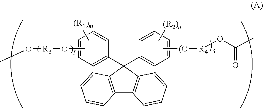
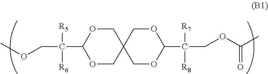
[0126]80.26 parts of 3,9-bis(2-hydroxy-1,1-dimethylethyl)-2,4,8,10-tetraoxaspiro[5.5]undecane (to be referred to as “spiroglycol” hereinafter), 51.41 parts of 9,9-bis(4-hydroxy-3-methylphenyl)fluorene (to be referred to as “BCF” hereinafter), 89.29 parts of diphenyl carbonate, and 1.8×10⁻² part of tetramethylammonium hydroxide and 1.6×10⁻⁴ part of sodium hydroxide as catalysts were heated at 180° C. in a nitrogen atmosphere to be molten. Thereafter, the degree of vacuum was set to 13.4 kPa over 30 minutes. Then, the temperature was raised to 260° C. at a rate of 60° C. / hr and maintained at that temperature for 10 minutes, and the degree of vacuum was set to 133 Pa or less over 1 hour. A reaction was carried out under agitation for a total of 6 hours. After the end of the reaction, tetrabutylphosphonium dodecylbenzenesulfonate was added in an amount that was 4 times the total molar amount of the catalysts to deactivate the catalysts, and the resulting pro...

example 2

Production of Optical Film

[0129]A film was produced in the same manner as in Example 1. The operation of Example 1 was repeated except that the obtained film was stretched to 2.5 times in the transverse direction to obtain a biaxially oriented film. The thickness, retardation, wavelength dispersion and Nz coefficient of this stretched film were measured. The results are shown in Table 1.

[0130]When the display screen of a liquid crystal panel which was produced by using the obtained stretched film in the same manner as in Example 1 was checked, it had good contrast and a wide view angle.

example 3

[0131]

[0132]The operation of Example 1 was repeated except that 85.13 parts of spiroglycol, 45.37 parts of BCF and 89.29 parts of diphenyl carbonate were used to obtain an aromatic-aliphatic copolycarbonate. The viscosity average molecular weight and glass transition temperature of the obtained pellet were measured, and the composition ratio of the pellet was measured by NMR. The results are shown in Table 1.

[0133]This copolymer was dissolved in methylene chloride to produce a dope having a solid content of 19 wt %. A cast film was produced from this dope solution by a known method. The operation of Example 1 was repeated to obtain a biaxially oriented film from this film. The thickness, retardation, wavelength dispersion and Nz coefficient of this stretched film were measured. The results are shown in Table 1.

[0134]When the display screen of a liquid crystal panel which was produced from the obtained stretched film in the same manner as in Example 1 was checked, it had good contras...


PUM

PropertyMeasurementUnit
wavelengthsaaaaaaaaaa

Abstract

An optical film having a desired wavelength dispersion characteristic, a low photoelastic coefficient and a desired Nz coefficient.The optical film is formed from a copolymer and meets the following conditions (i) to (v):(i) the thickness (d) is 20 to 80 μm;(ii) the following formulas (1) and (2) are satisfied:0.6<R(450) / R(550)<1  (1)1.01<R(650) / R(550)<1.40  (2)(R(450), R(550) and R(650) are retardations within the plane of the film at respective wavelengths);(iii) R(550) is 120 to 160 nm;(iv) the birefringence (Δn) is not less than 1.5×10⁻³; and(v) the Nz coefficient represented by the following formula (4) is 1.18 to 2.40:Nz=(nx−nz) / (nx−ny)  (4)(nx, ny and nz are 3-dimensional birefringences of the film).

Description

TECHNICAL FIELD[0001]The present invention relates to an optical film which has a desired wavelength dispersion characteristic and is used in a liquid crystal display or the like.BACKGROUND ART[0002]In general, an optical film, especially a retardation film is used in displays such as liquid crystal displays and has such functions as color correction, view angle expansion and antireflection.[0003]A λ / 4 plate and a λ / 2 plate are known as the retardation film, and thermoplastic polymers such as polycarbonate obtained by polycondensing bisphenol A, polyether sulfone and polysulfone are used as the materials of these plates. The λ / 4 plate and the λ / 2 plate obtained by stretching films of these materials are characterized in that their retardation becomes larger as the wavelength becomes shorter. Therefore, the wavelength at which the λ / 4 plate and the λ / 2 plate can function is limited to a specific wavelength.[0004]As means of controlling the wavelength at a broad band, there is known a...

Claims


Application Information

Patent Timeline
Patent Type & Authority Applications(United States)
IPC IPC(8): G02F1/13363G02B5/30
CPCC08G64/0208C08G64/1608C08J5/18G02F2001/133637G02B5/3083G02F1/133634C08J2369/00C09K2323/03G02F1/133637G02B5/30G02F1/1335
Inventor WASHIZU, AKIKOANDO, MASATOSHIMOTOYOSHI, TETSUYAMAEKAWA, SHOICHI
Owner TEIJIN KASEK KK
Why Eureka
Try Eureka