

Air purification system
- Summary
- Abstract
- Description
- Claims
- Application Information
AI Technical Summary
Benefits of technology
Problems solved by technology
Method used
Image

Examples
first exemplary embodiment
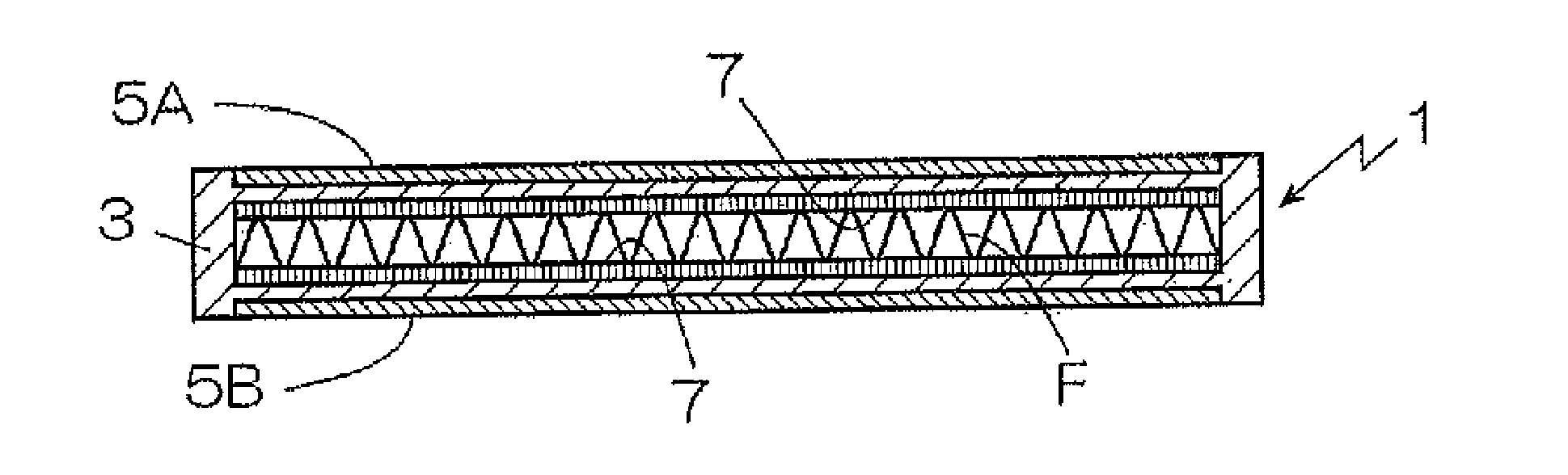
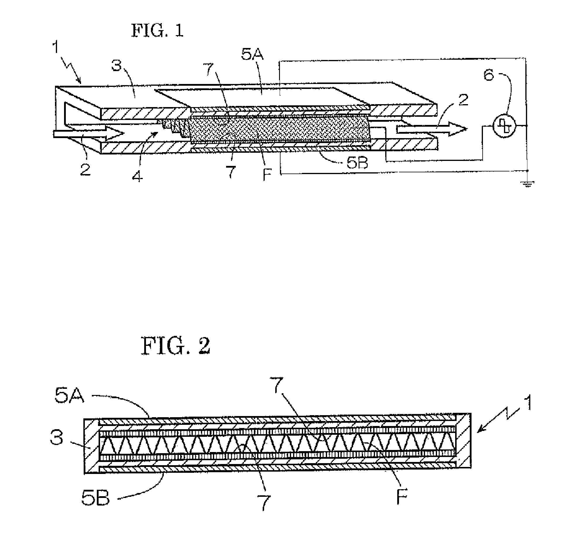
[0036]FIG. 1 is a schematic partial cut-away sectional diagram of an air purification system 1 according to a first exemplary embodiment, and FIG. 2 is a schematic vertical sectional diagram of the air purification system 1. The air purification system 1 includes a casing 3 made of an electrically non-conducting material and two plate-shaped electrodes 5A and 5B arranged on two opposing outer surfaces of the casing 3. The inside of the casing 3 is hollow and it constitutes an air passage 2 for passing air that needs to be purified. The electrodes 5A and 5B define a plasma generation zone 4 where plasma is generated in the air passage 2 within the casing 3.
[0037]A planar photocatalyst filter F is arranged in the plasma generation zone 4 such that it electrically contacts the opposing inner surfaces of the casing 3. A catalyst layer 7 (a catalyst body) is formed on one or both the inner surfaces of the casing 3 where the photocatalyst filter F touches the casing 3. The catalyst layer ...
second exemplary embodiment
[0067]FIG. 6 is a schematic sectional diagram of an air purification system 29 according to a second exemplary embodiment that differs in an electrical specification from the first exemplary embodiment. In the second exemplary embodiment, only the electrodes 5A and 5B are used as the plasma generation electrodes, i.e., the photocatalyst filter F is not used as the plasma generation electrode. That is, the electrodes 5A and 5B function as the plasma generation electrodes of opposite polarities.
[0068]Although the photocatalyst filter F is not used as the plasma generation electrode, because the photocatalyst filter F is in electrical contact with the casing 3, it will have the same electric potential as the electrodes 5A and 5B. Consequently, in the same manner as in the first exemplary embodiment, the electrode distance between the plasma generation electrodes of opposite polarities can be reduced and the effective electric discharge gap can be narrowed without physically making the ...
third exemplary embodiment
[0070]FIG. 7 is a schematic sectional diagram of an air purification system 30 according to a third exemplary embodiment that differs in an arrangement of electrodes from the first and second exemplary embodiments. The same reference numbers / symbols have been used for components that have the same structure or that perform the same function as those shown in FIG. 1, and the explanation of those reference numbers / symbols have been omitted.
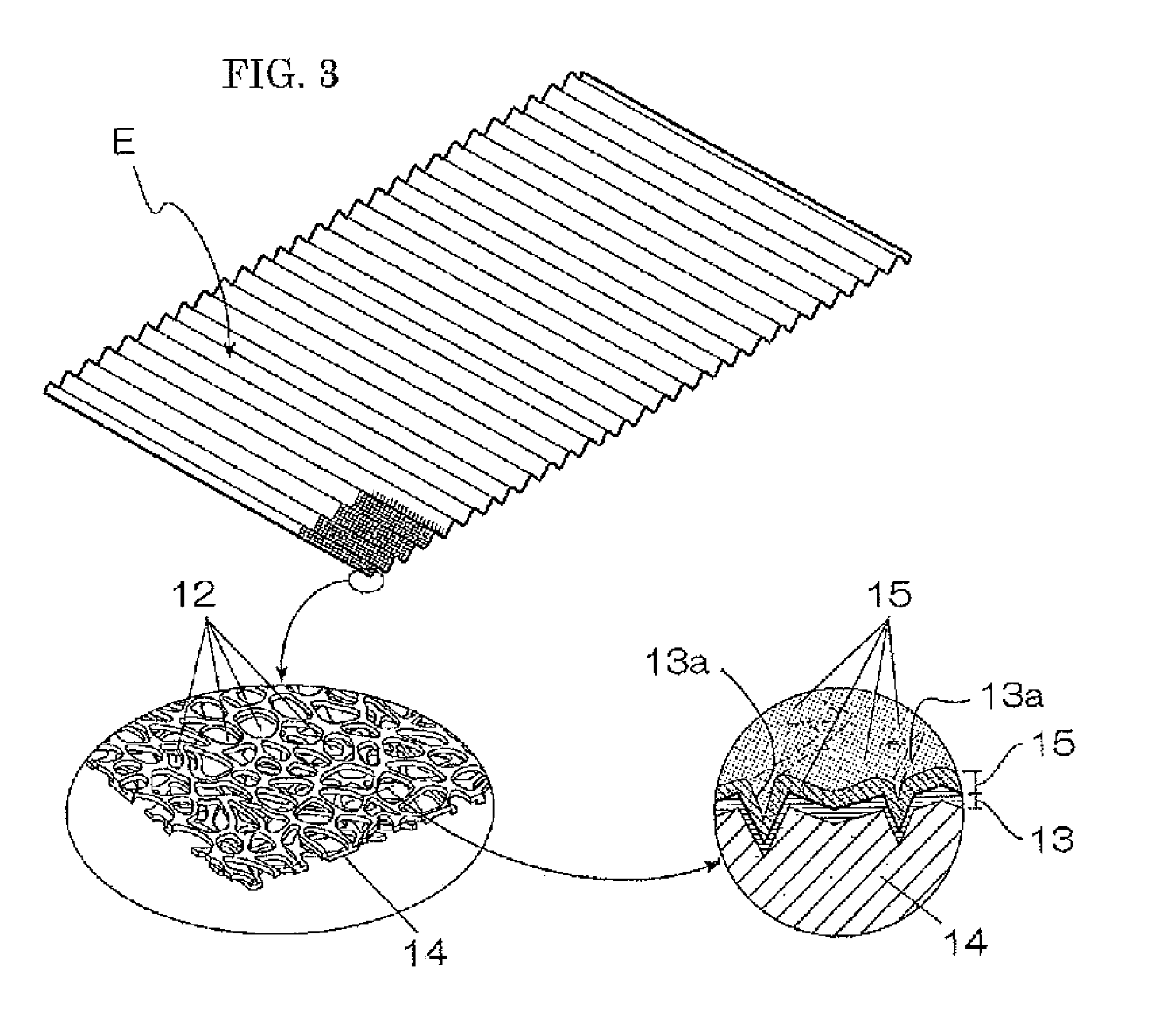
[0071]In the third exemplary embodiment, a catalyst filter C is arranged inside the plasma generation zone 4 in addition to the photocatalyst filter F. The catalyst filter C is impregnated with a non-photoexcitation type catalyst. The catalyst filter C includes a titanium mesh, or some other porous metal mesh, subjected to anodization processing, and the mesh is impregnated with the non-photoexcitation type catalyst. The catalyst can be platinum system, nickel system, oxide system depending on the pollutants that are to be removed from the air.
[0072...
PUM
| Property | Measurement | Unit |
|---|---|---|
| Polarity | aaaaa | aaaaa |
Abstract
Description
Claims
Application Information