Method And System For Removing Pollutants And Greenhouse Gases From A Flue Gas

a technology of flue gas and pollutants, applied in the direction of combustion process, combustion treatment, inorganic chemistry, etc., can solve the problems of affecting the combustion efficiency of combustion devices, affecting the use of these approaches, and affecting the environment and marine environment. , to achieve the effect of dramatic improvement of energy production efficiency

Inactive Publication Date: 2012-05-17
ECOSPEC GLOBAL TECH PTE LTD
View PDF0 Cites 15 Cited by
  • Summary
  • Abstract
  • Description
  • Claims
  • Application Information

AI Technical Summary

Benefits of technology

[0036]The most advantage of the invention is the generation of elemental products including elemental carbon and oxygen which can be recovered and reused again for combustion. This improves drastically the energy production efficiency for any carbon-based fuels. With such a recovery of energy, all carbonate-based substances such as minerals, limestone, dolomites or the like, including bicarbonates and carbonates present in the seawater or freshwater can be treated as an energy source. When their carbonate contents are converted into CO2 by acid treatment, the gas CO2 produced is then passing through the reactor to for conversion into elemental carbon and oxygen.
[0037]The objects, characteristics, advantages and technical effects of the invention will be further elaborated in the following description of the concepts and structures of the invention with reference to the accompanying drawings. The drawings illustrate the invention by way of examples without limitation to the invention in any manner.

Problems solved by technology

However, the use of these approaches would be hindered due to the high cost of low sulfur fuel premium and the availability of low sulfur fuel.
However, the use of lime in a dry or wet environment would lead to generation of CO2, because the lime CaO is typically obtained by heating limestone CaCO3 which results in releasing CO2.
The above processes are therefore harmful to the atmosphere and marine environments, although they all are able to remove the pollutant SO2.
These low NOx combustion devices all have a common disadvantage of compromising their combustion efficiencies due to the use of a lower combustion temperature.
However, the reduction in the combustion efficiency would require more fuel consumption or emit more CO2.
However, the performance of the catalysts may be affected by sulfur present in fuel oil or coal.
While in scrubbing processes in which lime is used, the generation of CaSO4 would also cause inactivation of the surface of the catalysts, in turn affect the removal of NOx.
However, these processes suffer from a serious problem that the storage for CO2 needs to be solved.
It is recognized that CO2 emission is in the order of trillion tons annually, and storing such a huge amount of the gas CO2 is costly and problematic.
Also, use of chemical neutralization and absorption has been proposed from removal of CO2, but disposal of final products from these processes is a crucial issue.
Therefore, they cannot be considered to be a solution against the removal of CO2.
However, this process is accompanied by generation of chlorine gas and HCl which are not allowed to be discharged directly by many regulations such as International Maritime Organization (IMO).
It would be obvious that such a process for removing CO2 is impractical due to the consumption of such high volume of alkaline water and energy as well as the huge size of an electrolytic tank.
However, the above processes and systems are either intended for removing one of the pollutants and greenhouse gases, or are not a practical solution.
This inevitably results in high capital cost, substantial footprint of the three separate plants, large storage space, and high cost of reagents, in additional to the issues of storage and disposal of final products.
The processes and systems mentioned above also show that none of them is able to re-utilize CO2 or final products as an energy source and they all relate to abetment technologies but not energy recovery technologies.

Method used


Image

  • Method And System For Removing Pollutants And Greenhouse Gases From A Flue Gas
  • Method And System For Removing Pollutants And Greenhouse Gases From A Flue Gas

Examples


example

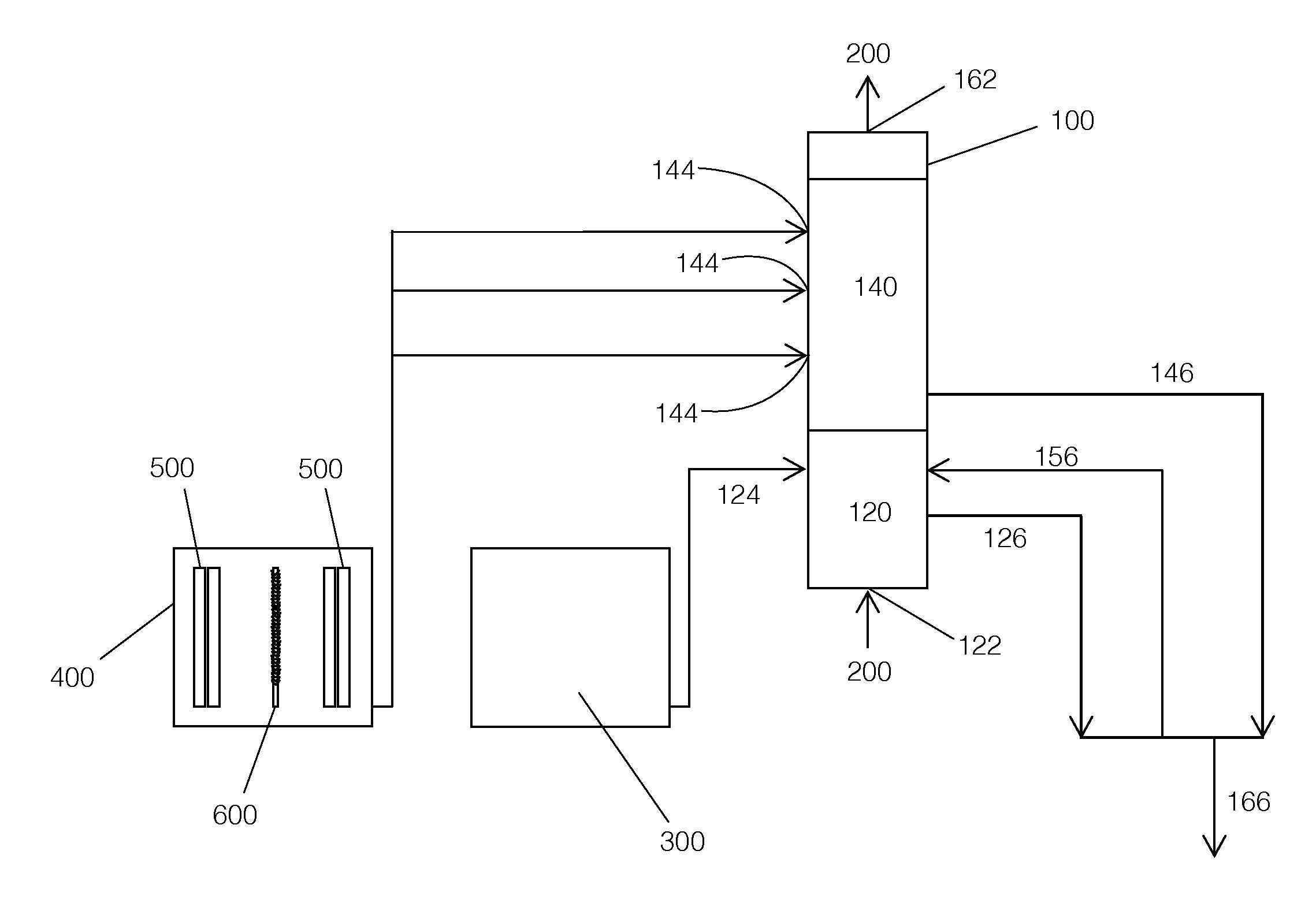
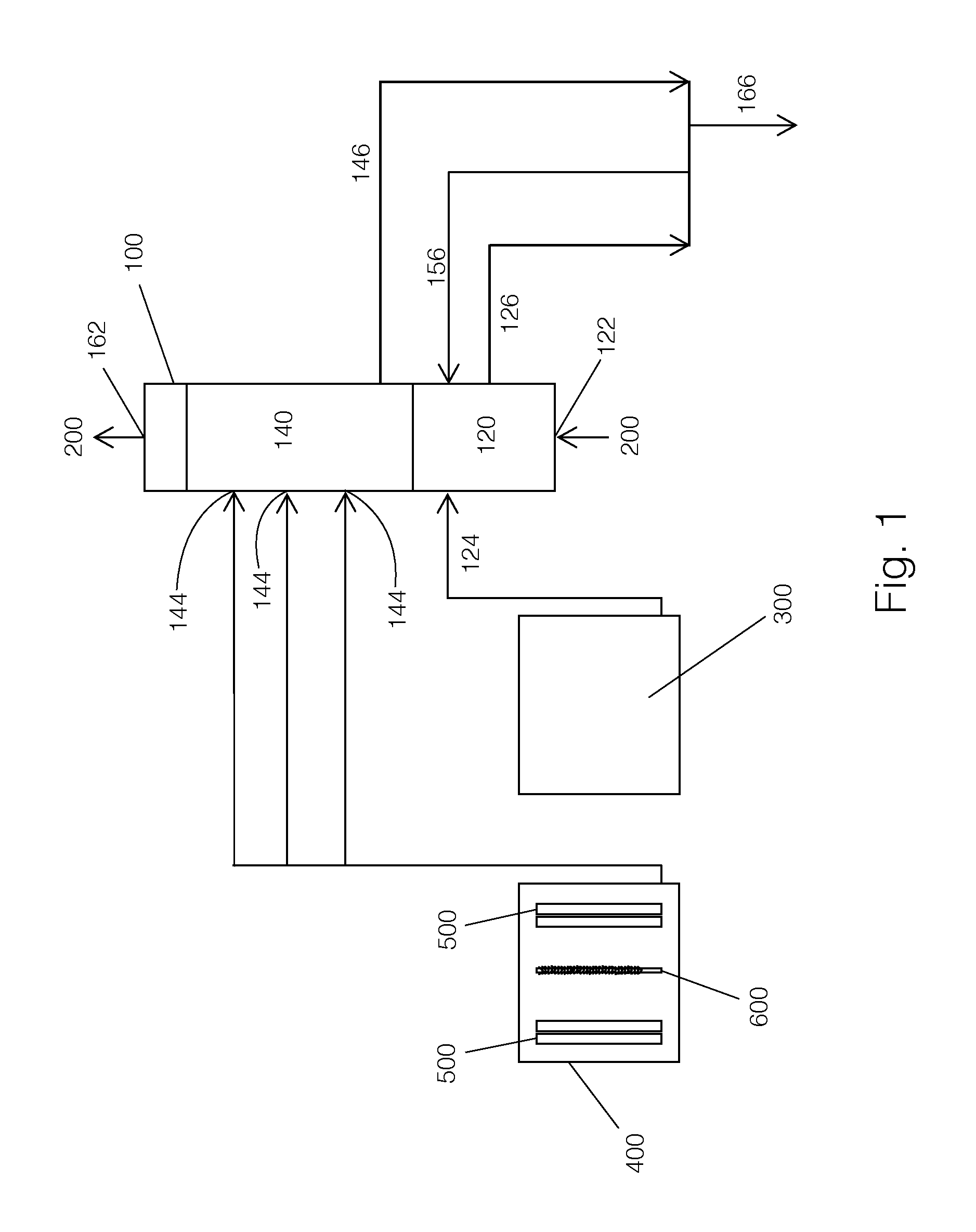
[0063]In various tests, the system shown in FIG. 1 is used to treat a flue gas under the conditions below:[0064]Height of tower: 7 to 11 m[0065]Height of the first stage: about 1 m[0066]Contact time between the flue gas and water: 25 seconds to 1 minutes[0067]Pressure of sea water: 2 to 8 bar[0068]pH of the treated alkaline water: 9.5 to 10[0069]Concentrations of components present in the flue gas: SO2: 10 to 2000 ppm[0070]NOx: 0 to 1000 ppm[0071]CO2: 2 to 7% by volume[0072]Temperature of the flue gas: 100 to 300° C.[0073]Flow rate of the flue gas: approximately 500 to 2500 m3 / h[0074]Flow rate of the natural seawater: approximately 10 to 25 m3 / h[0075]Flow rate of the treated alkaline water: approximately 5 to 25 m3 / h

[0076]The results of the tests showed that the removal of the gas SO2, NOx and CO2 are 80%-100%, 60%-80% and 20%-60%, respectively.

[0077]Thus, the present invention provides a method and a system which effectively remove the pollutants and greenhouse gases SO2, NOx and C...


PUM

PropertyMeasurementUnit
temperatureaaaaaaaaaa
pHaaaaaaaaaa
temperatureaaaaaaaaaa

Abstract

The invention relates to a method for removing pollutants and greenhouse gases SO2, NOx, and CO2 from a flue gas stream, comprising the steps of: a) contacting natural seawater with a flue gas in a counter flow, co-current flow or cross flow direction for a given period of time to remove SO2 from the flue gas; b) contacting treated alkaline water to the flue gas in a counter flow, co-current flow or cross flow direction to remove CO2 and NOx from the flue gas and generate oxygen and carbon particles; and c) collecting or emitting the flue gas after step b). The invention also relates to a system for removing pollutants and greenhouse gases SO2, NOx, and CO2 from a flue gas stream. The method and the system of the invention are significantly more economical and convenient and do not cause harm to the environments. The invention also exhibits a novel and unique feature that elemental carbon and oxygen are generated as final products and can be recovered as an energy source.

Description

FIELD OF THE INVENTION[0001]The present invention relates to a method and a system for removing pollutants and greenhouse gases, and more particularly, to a method and a system for simultaneously removing pollutants and greenhouse gases such as SO2, NOx, and CO2 from a flue gas through a combined effect of adsorption, bond breaking end result alike reaction and time varying low frequency electromagnetic wave treatment.BACKGROUND OF THE INVENTION[0002]In many industries including onshore, offshore industries, land, sea and air transportation, a flue gas containing pollutants and greenhouse gases such as SO2, NOx and CO2 is usually generated and needs to be treated to comply with the emission standards requisitioned by various environmental authorities and international organization.[0003]Presently, control measures for removing SO2, NOx and CO2 from the flue gas are discussed as follows.[0004]To reduce SO2 emission, the approaches in existence are typically to use low sulfur fuel if ...

Claims


Application Information

Patent Timeline
Patent Type & Authority Applications(United States)
IPC IPC(8): B01D53/62B01D53/74C01B31/02
CPCB01D53/60B01D53/62B01D53/75B01D53/78B01D2251/304B01D2251/402Y02C10/04B01D2251/606B01D2257/302B01D2257/404B01D2257/504B01D2258/012B01D2258/0283B01D2251/404Y02A50/20Y02C20/40
Inventor CHEW, HWEE HONG
Owner ECOSPEC GLOBAL TECH PTE LTD
Why Eureka
Try Eureka