Film deposition system and method and gas supplying apparatus being used therein

Inactive Publication Date: 2012-05-17
IND TECH RES INST
View PDF0 Cites 0 Cited by
  • Summary
  • Abstract
  • Description
  • Claims
  • Application Information

AI Technical Summary

Benefits of technology

[0005]The present disclosure related to a film deposition system and method, in that gas supplying apparatuses will first enable their corresponding precursors to be atomized and then enable the atomized precursors to be vaporized into high-concentration and high-capacity vapor precursors so as to be fed into a process chamber in respective, and thereafter, inside the process chamber, the high-concentration and high-capacity vapor precursors are premixed using a showerhead module before being uniformly distributed onto a surface of a substrate for achieving not only the increasing in film deposition rate while simultaneously enhancing the uniformity of the film being deposited on a large-area substrate by the use of the showerhead module. Thereby, the characteristic of transparent conductive film being deposited thereby can be ensured for the transparency thereof is improved and the sheet resistance thereof can be reduced while the uniform of the thickness are enhanced effectively.
[0006]The present disclosure also relates to a gas supplying apparatus, capable of first atomizing a precursor and then enabling the atomized precursor to be heated and thus vaporized into a vapor precursor so as to be transported using a flow of a specific amount of a carrier gas for outputting the vapor precursor with high concentration and high capacity.

Problems solved by technology

Nevertheless, for the PVD film deposition, since the texturing of the resulting films is usually performed by means of etching, it is disadvantageous not only in terms of increasing process complexity, but also in terms of lower deposition ratio due to the use of the PVD process.
On the other hand, for the CVD film deposition, since it is required to enable the precursors to be fed into the showerhead module inside the reaction chamber with the flowing of carrier gases, it is disadvantageous not only in terms of low concentration of precursors in carrier gases, but also in terms of decreasing deposition speed due to the low concentration.
However, since the vapor precursors being fed into the reaction chamber using the aforesaid gas supplying apparatuses are low in concentration and also low in capacity, causing low deposition efficiency and low film growth rate as the consequence, the manufacturing cost of the aforesaid film deposition system can be comparatively higher.
However, although the chemical reactions for film deposition are enhanced by the energized precursors, the capacity of the precursor being transported is still not improved and thus the film deposition efficiency is still unsatisfactory.

Method used


Image

  • Film deposition system and method and gas supplying apparatus being used therein
  • Film deposition system and method and gas supplying apparatus being used therein
  • Film deposition system and method and gas supplying apparatus being used therein

Examples


Embodiment Construction

[0017]For your esteemed members of reviewing committee to further understand and recognize the fulfilled functions and structural characteristics of the disclosure, several exemplary embodiments cooperating with detailed description are presented as the follows.

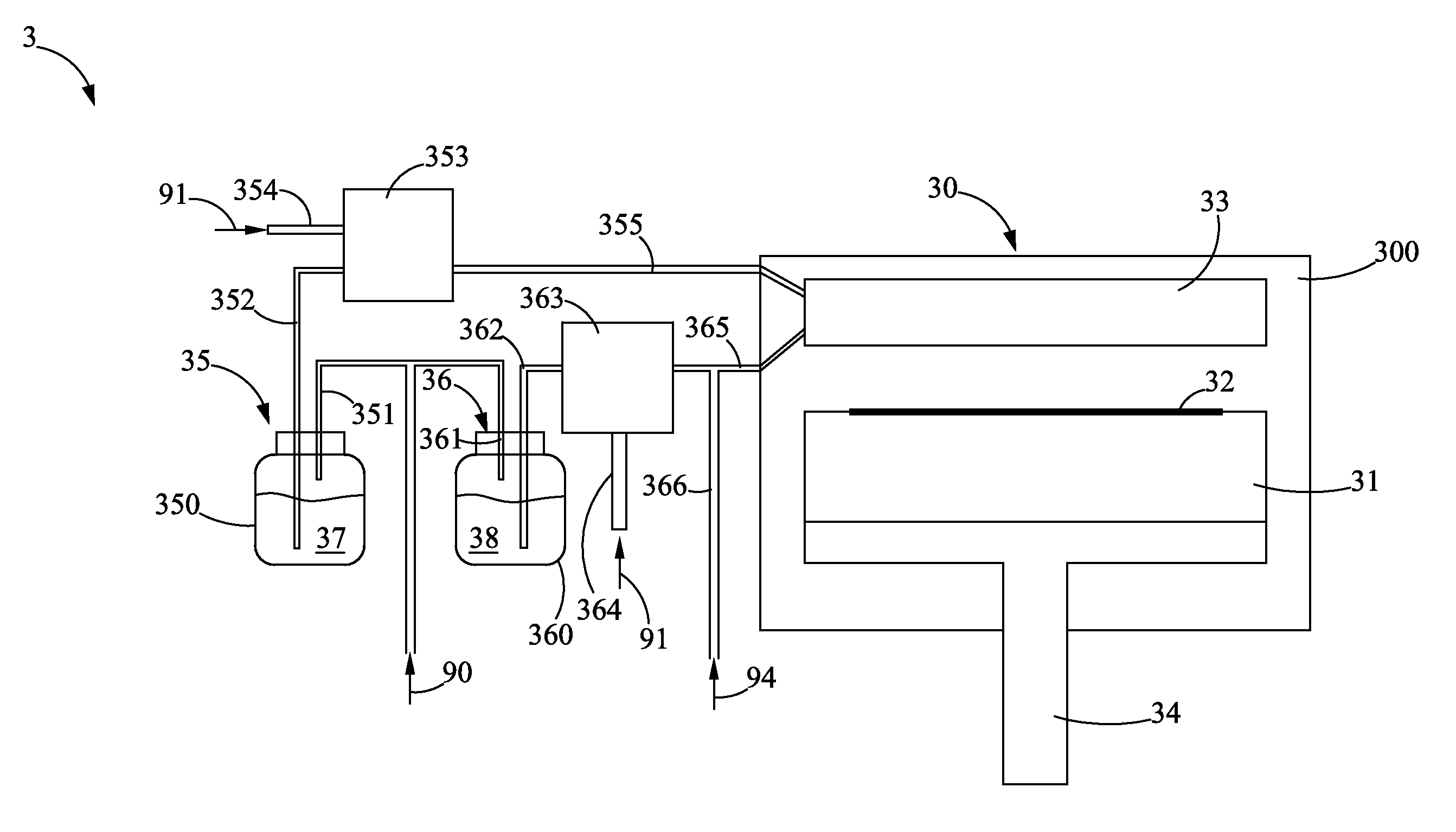
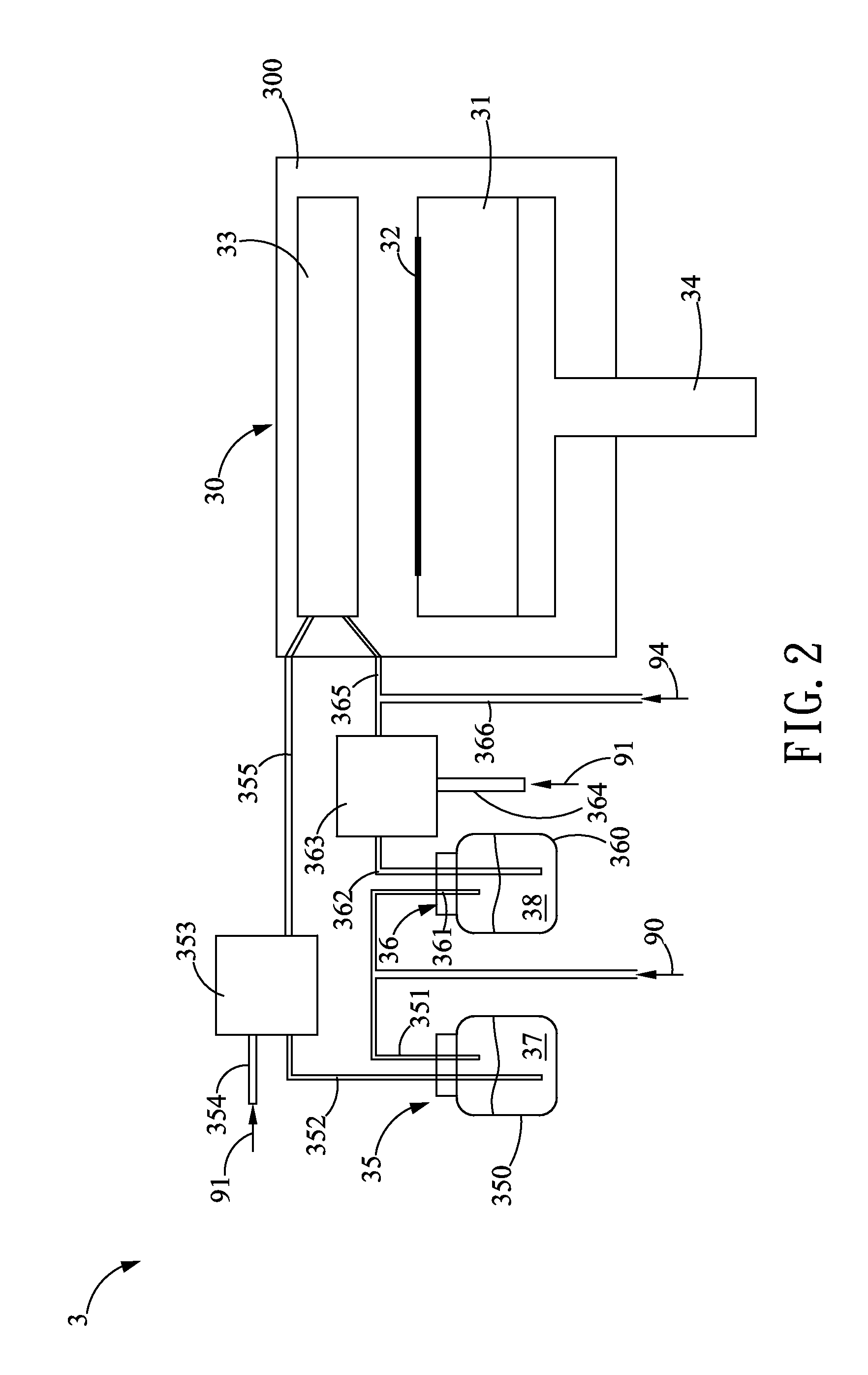
[0018]Please refer to FIG. 2, which is a schematic diagram showing a film deposition system according to the present disclosure. In FIG. 2, the film deposition system 3 comprises a film deposition apparatus 30 and a plurality of gas supplying apparatuses, in which the film deposition apparatus 30 is formed with a process chamber 300, whereas the process chamber 300 has a heater 31 disposed therein, that is provided for a substrate 32 to be disposed thereon. It is noted that the substrate 32 can be a silicon substrate or a glass substrate, but is not limited thereby. Moreover, inside the process chamber 300, there is a showerhead module 33 being disposed at a position above the heater 31 while being connected to the plural gas...


PUM

PropertyMeasurementUnit
Pressureaaaaaaaaaa
Concentrationaaaaaaaaaa
Metallic bondaaaaaaaaaa

Abstract

The present invention provides a film deposition system and method by combining a plurality of gas supplying apparatuses and a deposition apparatus being in communication with the plurality of gas supplying apparatuses. By means of respectively providing different types of vapor precursors with high concentration and high capacity into a process chamber of the deposition apparatus through the plurality of gas supplying apparatus, the deposition reaction is accelerated so as to improve the efficiency of film deposition. In an embodiment of the gas supplying apparatus, it utilizes a first gas for providing high pressure toward on a liquid surface of the precursor, thereby transporting the precursor into an atomizing and heating unit whereby the precursor is atomized and then is heated so as to form a high-concentration and high capacity vapor precursor transported by another carrier gas.

Description

CROSS-REFERENCE TO RELATED APPLICATIONS[0001]This non-provisional application claims priority under 35 U.S.C. §119(a) on Patent Application No(s). 099139329 filed in Taiwan, R.O.C. on Nov. 16, 2010, the entire contents of which are hereby incorporated by reference.TECHNICAL FIELD[0002]The present disclosure relates to a film depositing technique, and more particularly, to a film deposition system and method and gas supplying apparatus being used therein.TECHNICAL BACKGROUND[0003]Generally, the deposition of transparent conductive film in solar cell production is performed either by means of physical vapor deposition (PVD) or by means of chemical vapor deposition (CVD). Nevertheless, for the PVD film deposition, since the texturing of the resulting films is usually performed by means of etching, it is disadvantageous not only in terms of increasing process complexity, but also in terms of lower deposition ratio due to the use of the PVD process. On the other hand, for the CVD film de...

Claims


Application Information

Patent Timeline
IPC IPC(8): C23C16/455F15D1/00C23C16/18C23C16/448C23C16/46
CPCC23C16/18C23C16/4486C23C16/4482Y10T137/6416
Inventor CHIANG, MING-TUNGLIN, SHIH-CHIN
Owner IND TECH RES INST
Why Eureka
Try Eureka