Method of forming silicon nitride films

a technology of silicon nitride and film, which is applied in the direction of plasma technique, metal material coating process, coating, etc., can solve the problems of low film deposition rate of silicon nitride film-forming method, impede efficient production, and not achieve high enough film deposition ra

Inactive Publication Date: 2009-04-02
FUJIFILM CORP
View PDF9 Cites 3 Cited by
  • Summary
  • Abstract
  • Description
  • Claims
  • Application Information

AI Technical Summary

Benefits of technology

[0056]The flow rate of the nitrogen gas is preferably 1 to 5 times the total flow rate of the silane gas and the ammonia gas.
[0057]By setting the flow rate of the nitrogen gas to not less than the total flow rate of the silane gas and the ammonia gas, the film deposition rate can be advantageously improved in a consistent manner owing to the introduction of the nitrogen gas. In addition, by setting the flow rate of the nitrogen gas to up to 5 times the total flow rate of the silane gas and the ammonia gas, more preferable results are obtained in terms of, for example, uniformity in film thickness distribution.
[0058]In the method of the invention to form a silicon nitride film, the total flow rate of the silane gas and the ammonia gas is not particularly limited but may be appropriately determined according to the required film deposition rate and film thickness.
[0059]According to the study made by the inventor of the invention, the total flow rate of the silane gas and the ammonia gas is preferably from 1 to 10,000 sccm and more preferably from 100 to 5,000 sccm.
[0060]By adjusting the total flow rate of the silane gas and the ammonia gas within the above-defined range, preferable results are obtained in terms of, for example, productivity and discharge stability.
[0061]The ratio of the flow rate of the ammonia gas to that of the silane gas is also not limited to any particular value, but may be appropriately set according to the composition (compositional ratio) of the silicon nitride film to be formed.

Problems solved by technology

However, because the nitrogen gas used as the gas material has a low activity, this silicon nitride film-forming method is low in film deposition rate.
A high enough film deposition rate is not achieved even by using highly reactive ammonia gas as the gas material.
Therefore, as described above, equipment where film deposition is continuously carried out as an elongated substrate such as a polymer film is transported in a longitudinal direction requires slowing down the travel speed of the substrate, which hampers efficient production.

Method used


Image

  • Method of forming silicon nitride films
  • Method of forming silicon nitride films
  • Method of forming silicon nitride films

Examples


example 1

[0083]A common CVD device based on an ICP-CVD process was used to form a silicon nitride film on a substrate.

[0084]The substrate used was a polyester film with a thickness of 188 μm (polyethylene terephthalate film “Luminice” manufactured by Toray Advanced Film Co., Ltd.).

[0085]The substrate was set at a predetermined position within a vacuum chamber, and the vacuum chamber was closed.

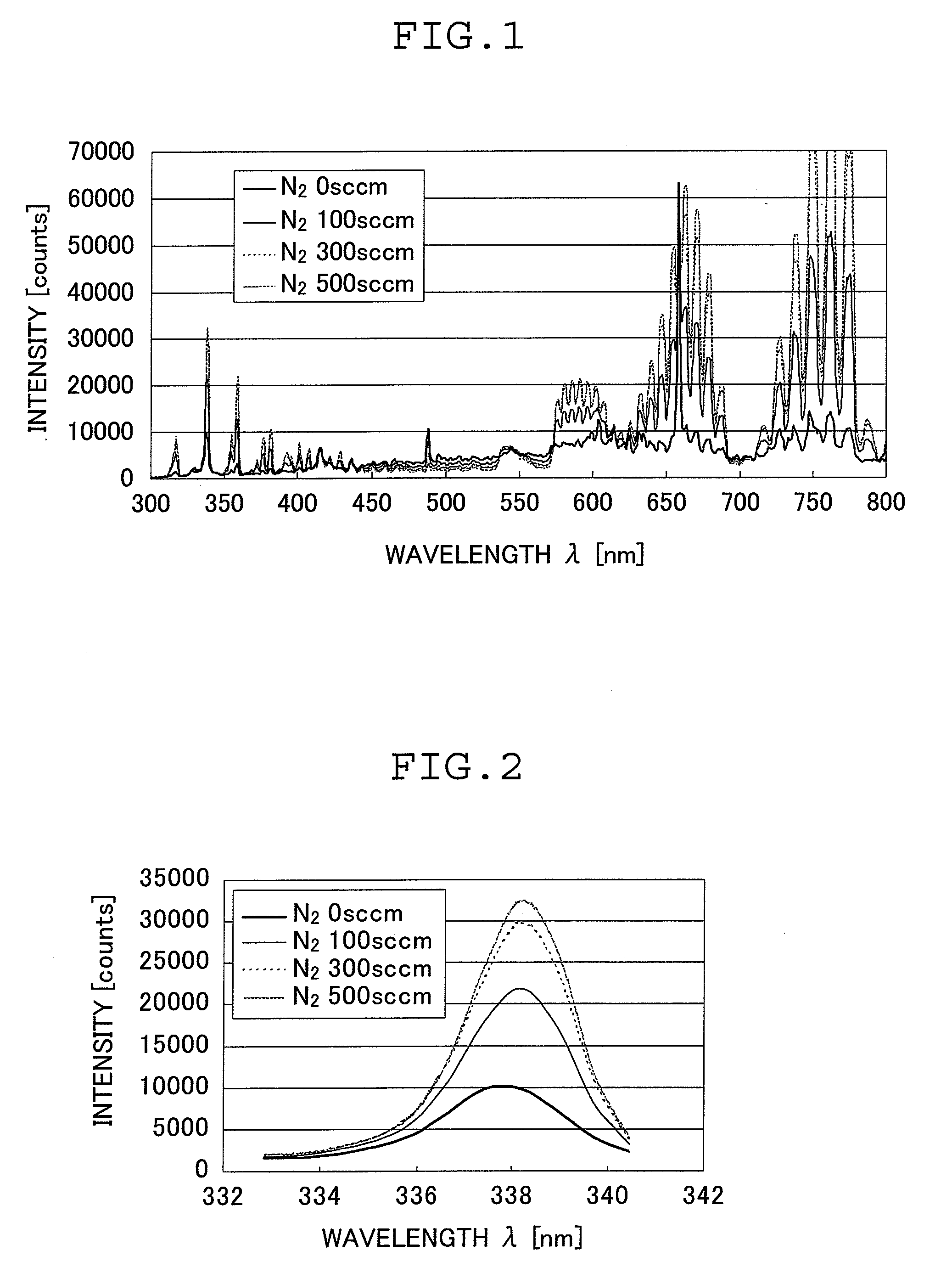
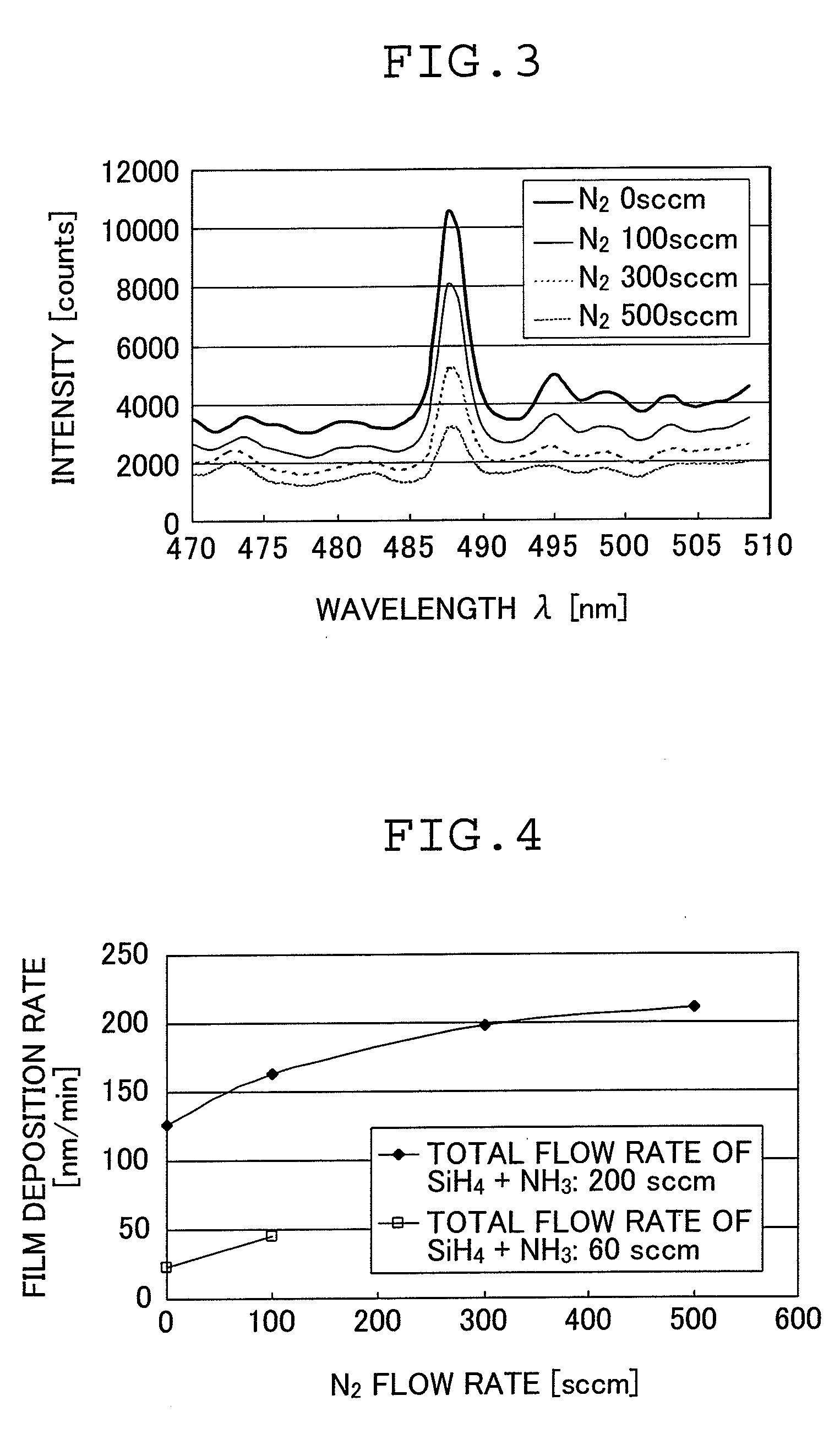
[0086]Then, the vacuum chamber was evacuated to reduce the internal pressure. When the internal pressure had reached 7×10⁻⁴ Pa, silane gas, ammonia gas and nitrogen gas were introduced into the vacuum chamber. The silane gas and the ammonia gas were introduced at flow rates of 50 sccm and 150 sccm, respectively (total flow rate: 200 sccm).

[0087]Evacuation of the vacuum chamber was adjusted so that the vacuum chamber had an internal pressure of 3 Pa.

[0088]Then, 2 kW RF power was supplied to an induction coil and a silicon nitride film was formed on the surface of the substrate by ICP-CVD. During the fil...

example 2

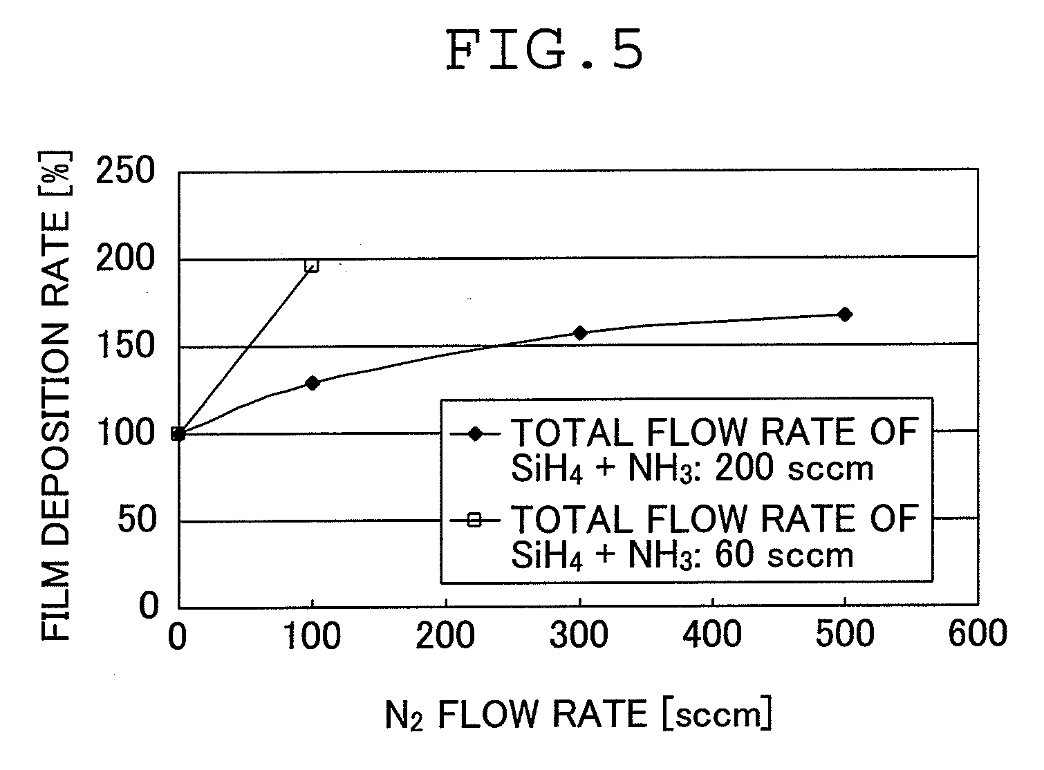
[0092]Example 1 was repeated except that the silane gas and the ammonia gas were introduced at flow rates of 15 sccm and 45 sccm, respectively (at a total flow rate of 60 sccm) to thereby determine the relation between the nitrogen gas flow rate and the film deposition rate.

[0093]It should be noted that the nitrogen gas was introduced at flow rates of 0 sccm and 100 sccm (the nitrogen gas flow rate being about 1.67 times the total flow rate of the silane gas and the ammonia gas), respectively.

[0094]The flow rate is shown in FIG. 4 and the film deposition rate at a nitrogen gas flow rate of 100 sccm with respect to the nitrogen gas flow rate of 0 sccm taken as 100% is shown in FIG. 5.

[0095]As is seen from FIGS. 4 and 5, by forming a silicon nitride film through ICP-CVD using the gas material including the silane gas, ammonia gas and nitrogen gas, the film deposition rate can be considerably improved compared with cases where no nitrogen gas is used.

[0096]In the case where the total f...


PUM

PropertyMeasurementUnit
temperatureaaaaaaaaaa
pressureaaaaaaaaaa
temperatureaaaaaaaaaa

Abstract

The silicon nitride film-forming method includes a step of supplying a gas material including silane gas, ammonia gas and nitrogen gas in such a manner that a flow rate of the nitrogen gas is 0.2 to 20 times a total flow rate of the silane gas and the ammonia gas, and a step of carrying out inductively coupled plasma-enhanced chemical vapor deposition to form a silicon nitride film. This method is capable of forming a silicon nitride film at a high film deposition rate.

Description

[0001]The entire contents of a document cited in this specification are incorporated herein by reference.BACKGROUND OF THE INVENTION[0002]The present invention relates to the technical field of forming silicon nitride films by plasma-enhanced chemical vapor deposition (CVD). The invention more specifically relates to a silicon nitride film-forming method capable of film formation at a high film deposition rate through inductively coupled plasma-enhanced chemical vapor deposition.[0003]Silicon nitride films are employed as water vapor barrier films in various devices and optical elements requiring moisture resistance, and protective films (passivation films) and insulating films in semiconductor devices.[0004]Plasma-enhanced CVD is used in methods of forming silicon nitride films.[0005]A known technique of film formation by plasma-enhanced CVD is capacitively coupled plasma-enhanced chemical vapor deposition (hereinafter abbreviated as “CCP-CVD”), which is a technique involving apply...

Claims


Application Information

Patent Timeline
Patent Type & Authority Applications(United States)
IPC IPC(8): H05H1/24
CPCC23C16/507C23C16/345
Inventor TAKAHASHI, TOSHIYA
Owner FUJIFILM CORP
Why Eureka
Try Eureka