Wireless communication system and method for wireless communication
a wireless communication and wireless communication technology, applied in the direction of electrical equipment, power management, network topologies, etc., can solve the problems of increasing the load on the network, the uplink signal sent from the mobile terminal becomes a very intense interference signal, etc., and achieve the effect of improving the overall system, increasing the load on the base station
- Summary
- Abstract
- Description
- Claims
- Application Information
AI Technical Summary
Benefits of technology
Problems solved by technology
Method used
Image

Examples
first embodiment
1. First Embodiment
[0047]Referring to the drawings, a first embodiment of the present invention will be described below.
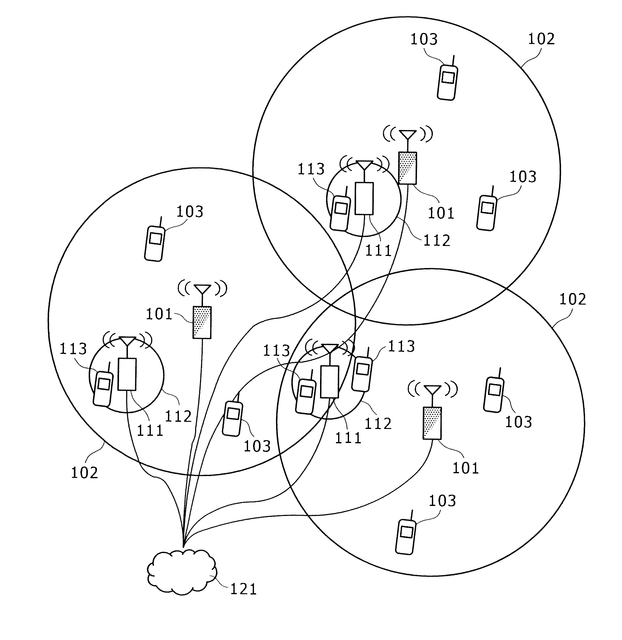
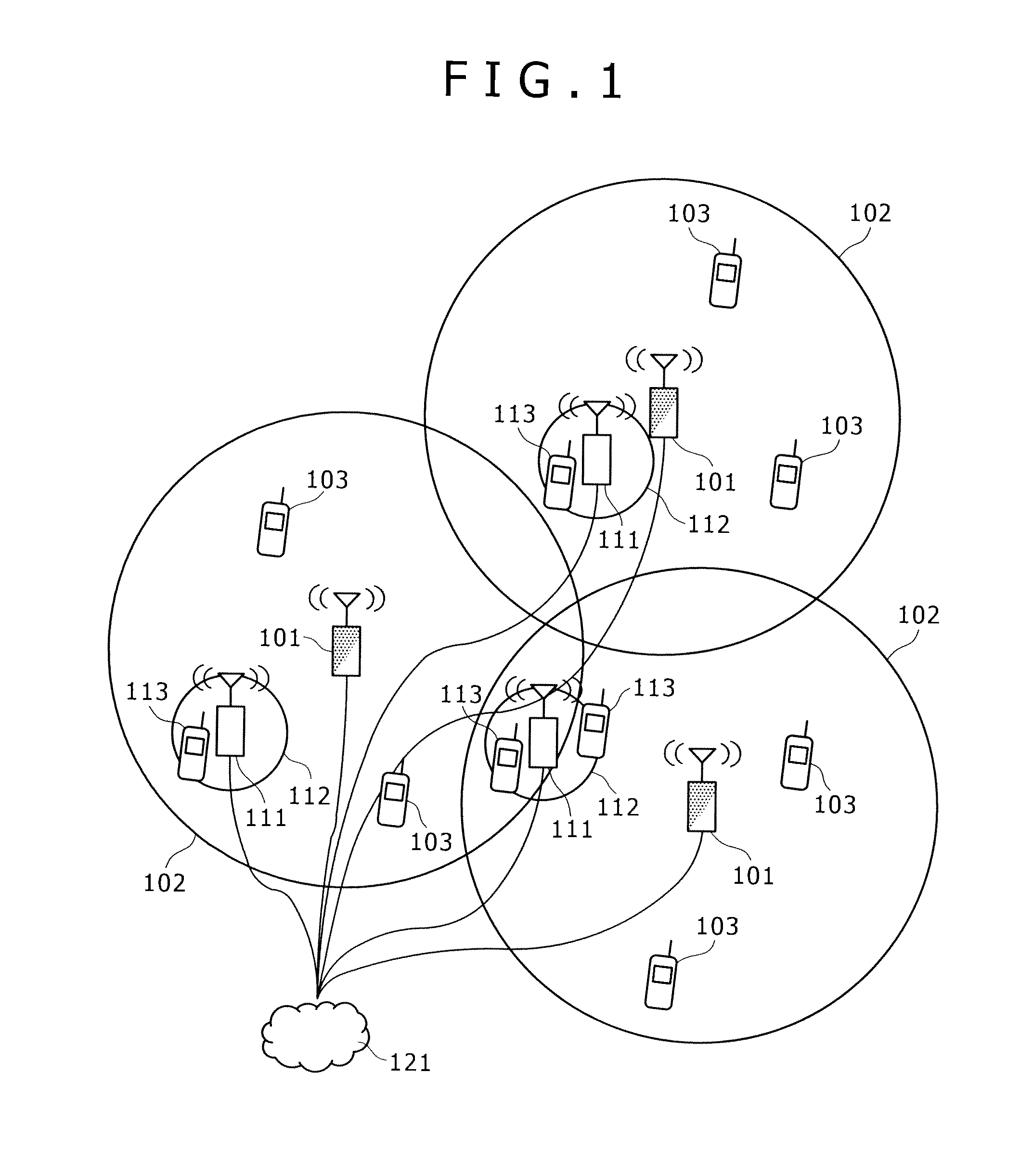
[0048]FIG. 1 is a diagram showing an example of the configuration of a cellular wireless communication system in accordance with the first embodiment of the present invention including femto cell base stations.
[0049]In the present system, a macro cell base station 101 forms a macro cell 102, and one or more mobile terminals 103 exist in the macro cell 102. The macro cell base station 101 and mobile terminals 103 are connected to one another over wireless links.
[0050]A femto cell base station 111 installed in the macro cell 102 forms a femto cell 112, and one or more mobile terminals 113 exist in the femto cell 112. The femto cell base station 111 and mobile terminals 113 are connected to one another over wireless links.
[0051]The macro cell base station 101 and femto cell base station 111 are connected to a core network 121 over wired links.
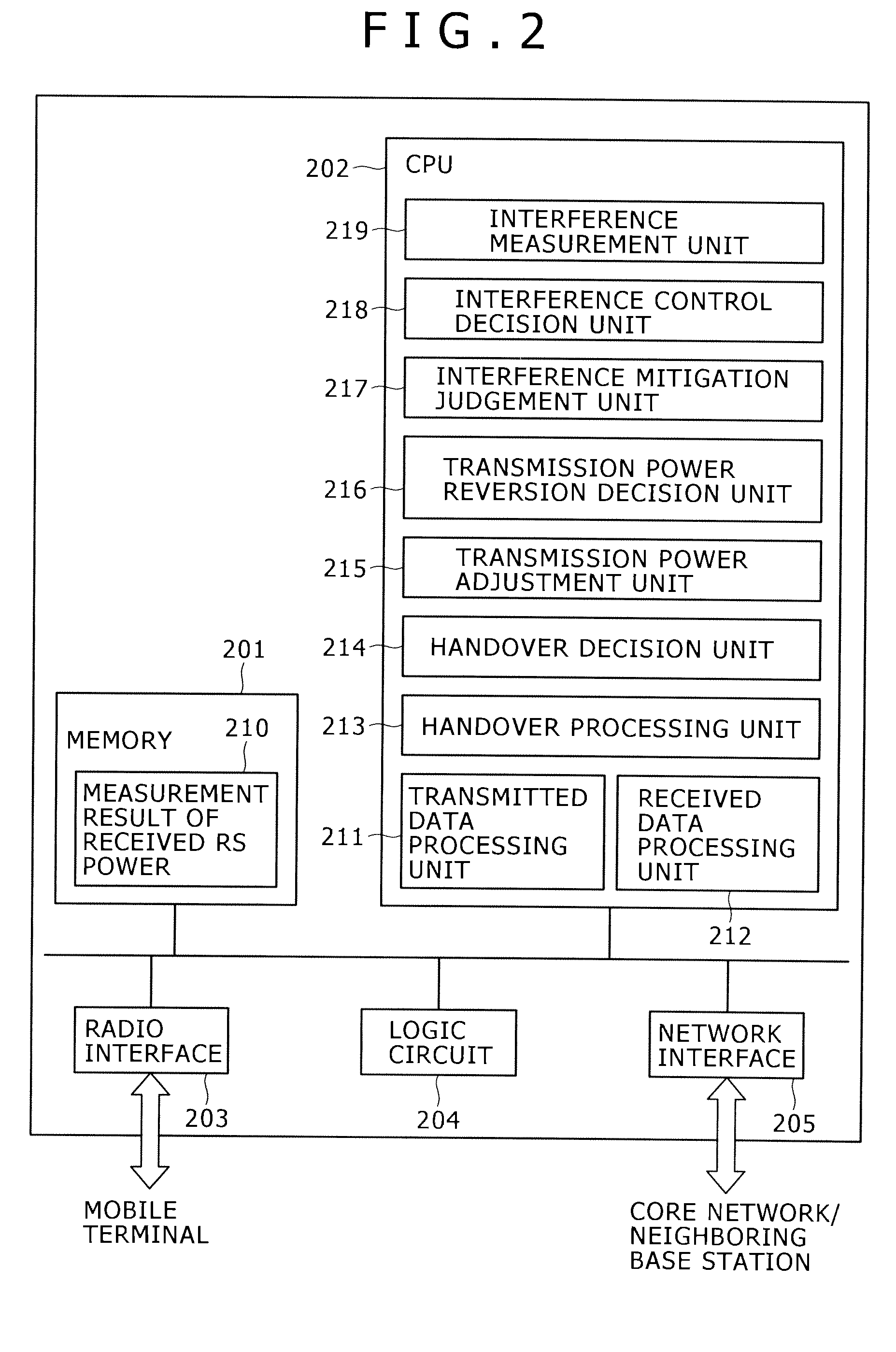
[0052]FIG. 2 shows an exa...
second embodiment
2. Second Embodiment
[0121]Now, a second embodiment of the present invention will be described below.
[0122]The present embodiment is different from the first embodiment in actions to be performed at step 1006 and subsequent steps. In particular, actions for handover necessity decision (step 1010′) and for power decrease (step 1012′) are different from those of steps 1010 and 1012 in the first embodiment. In addition, since the action for handover necessity decision (step 1010′) is different, an uplink interference control action sequence is different.
[0123]FIG. 6B shows an uplink interference control sequence to be followed by the femto cell base station 111.
[0124]Actions of steps 1001 to 1004 are identical to those in the first embodiment mentioned in FIG. 6A.
[0125]The femto cell base station 111 and macro cell base station 101 each regularly transmit a downlink RS. Therefore, an opportunity to transmit the downlink RS from each base station succeeds to step 1004 (steps 1006 and 100...
third embodiment
3. Third Embodiment
[0139]A third embodiment of the present invention will be described below. In the present embodiment, a sequence for uplink interference control to be followed by the femto cell base station 111 is, as mentioned in FIG. 6B, identical to that in the second embodiment, but actions at steps 1010′ and 1012′ are different from those in the second embodiment.
[0140]FIG. 10 is a flowchart of step 1010′ in the third embodiment of the present invention.
[0141]The interference mitigation judgment unit 217 decides whether a difference between a downlink RS receiving power that is relevant to the femto cell base station 111 and notified by a mobile terminal at step 1009 in FIG. 6B, and a downlink RS receiving power relevant to the macro cell base station 101 is equal to or larger than a predetermined threshold “c” (step 2201), and passes the result of the decision to the handover decision unit 214.
[0142]If it is found as a result of step 2201 that the difference between the dow...
PUM
 Abstract
Description
Claims
Application Information
 - R&D
- Intellectual Property
- Life Sciences
- Materials
- Tech Scout
- Unparalleled Data Quality
- Higher Quality Content
- 60% Fewer Hallucinations
Browse by: Latest US Patents, China's latest patents, Technical Efficacy Thesaurus, Application Domain, Technology Topic, Popular Technical Reports.
© 2025 PatSnap. All rights reserved.Legal|Privacy policy|Modern Slavery Act Transparency Statement|Sitemap|About US| Contact US: help@patsnap.com