Fluid injection

a technology of fluid injection and injection chamber, which is applied in the field of fluid injection systems and methods, can solve problems such as difficulty in control

Active Publication Date: 2012-05-31
PRESIDENT & FELLOWS OF HARVARD COLLEGE
View PDF7 Cites 219 Cited by
  • Summary
  • Abstract
  • Description
  • Claims
  • Application Information

AI Technical Summary

Benefits of technology

[0013]The method, in still another set of embodiments, includes acts of providing a microfluidic system comprising a first microfluidic channel and a second microfluidic channel contacting the first microfluidic channel at an intersection, providing a first fluid in the first microfluidic channel and a second fluid in the second microfluidic channel, and urging fluid from the fir

Problems solved by technology

While droplet coalescence has been demonstrated f

Method used


Image

  • Fluid injection
  • Fluid injection
  • Fluid injection

Examples


example 1

EXAMPLE 1

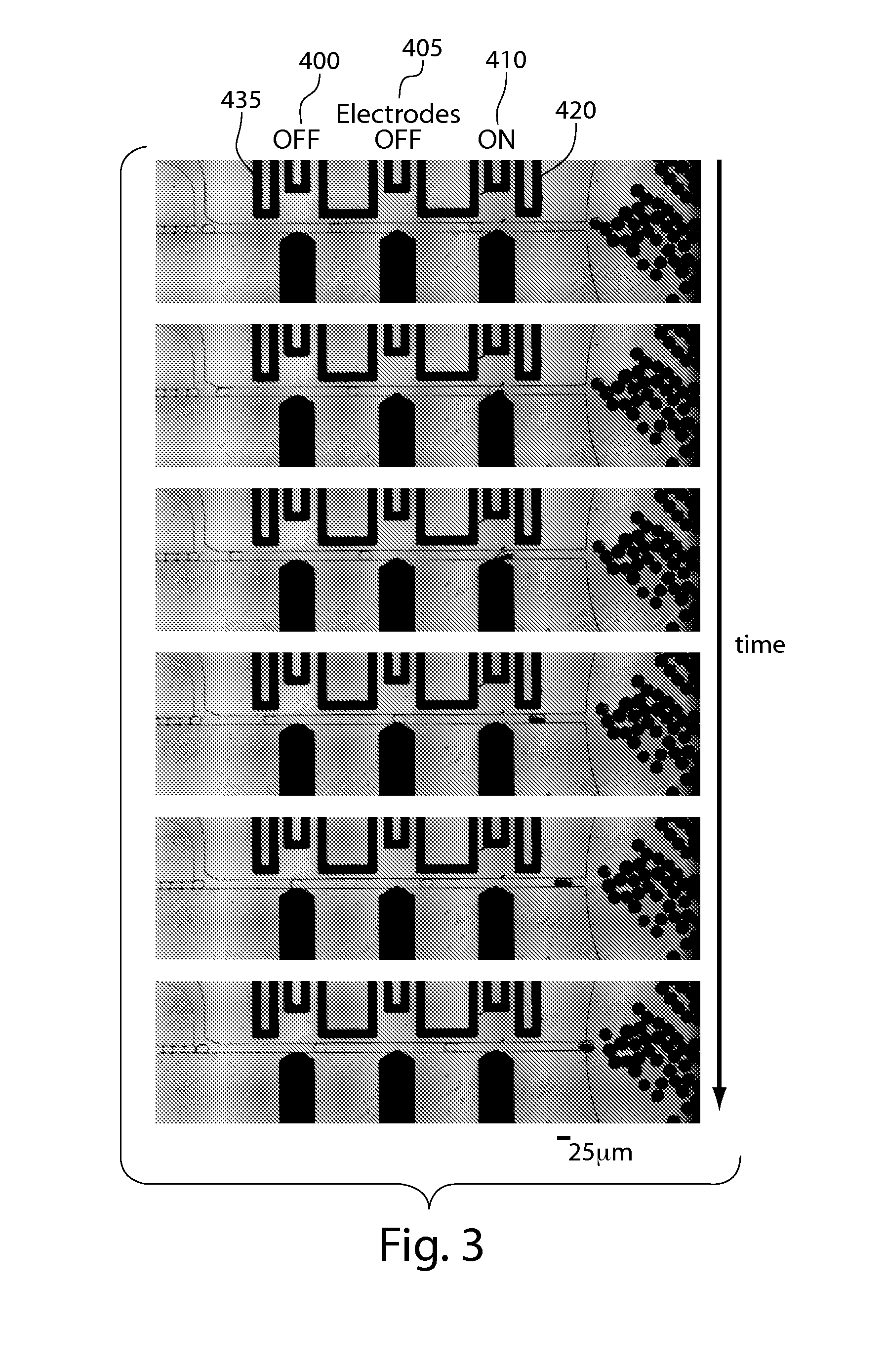
[0128]This example demonstrates fluid injection into fluidic droplets. In each of Examples 1, 2, and 3, single-layer PDMS microfluidic devices such as those shown in FIGS. 4A and 4B were fabricated. In these examples, water-in-oil emulsion droplets with relatively low polydispersity flowed past the orifice where an electric field was applied to cause injection of a bromophenol dyed fluid into the droplets. The droplets passed through a serpentine channel (e.g., as shown in FIGS. 4A and 4B) where the bromophenol dye mixed with the fluid inside the droplets. The droplets then flowed past a laser beam / PMT (photomultiplier tube) setup and microscope camera, both of which captured the light intensity inside the droplets. Since the volume of each droplet prior to injection is known and essentially the same, the amount of bromophenol dyed fluid injected could be determined from the change in intensity of the droplet after injection. Measurements from the PMT / laser were compared t...

example 2

EXAMPLE 2

[0129]This example demonstrates control of fluid injection by varying the continuous phase (i.e., the “outer phase”) flow rate. A system similar to that discussed in Example 1 was used for this example. The outer phase flow rate was set by a volume-driven syringe pump and was varied while keeping the other operating conditions (i.e., applied voltage) constant. As shown in FIG. 7A, as the outer phase flow rate increased, the residence time of droplets decreased, resulting in a decrease in the volume of fluid injected. Thus, by controlling the outer phase flow rate, the amount of fluid injected into the droplets could be readily controlled.

example 3

EXAMPLE 3

[0130]This example demonstrates control of fluid injection by varying the injection pressure. A system similar to that discussed in Example 1 was used for this example. The fluid tubing leading into the second channel containing a bromophenol dye was placed in a pressure tight basin fed by regulator-controlled pressurized air. As the injection pressure increased, the injection volume increased, as shown in FIG. 7B (pressure in units of ps). Accordingly, by controlling the injection pressure, the amount of fluid injected into the droplets could be readily controlled.


PUM


Abstract

The present invention generally relates to systems and methods for the control of fluids and, in some cases, to systems and methods for flowing a fluid into and/or out of other fluids. As examples, fluid may be injected into a droplet contained within a fluidic channel, or a fluid may be injected into a fluidic channel to create a droplet. In some embodiments, electrodes may be used to apply an electric field to one or more fluidic channels, e.g., proximate an intersection of at least two fluidic channels. For instance, a first fluid may be urged into and/or out of a second fluid, facilitated by the electric field. The electric field, in some cases, may disrupt an interface between a first fluid and at least one other fluid. Properties such as the volume, flow rate, etc. of a first fluid being urged into and/or out of a second fluid can be controlled by controlling various properties of the fluid and/or a fluidic droplet, for example curvature of the fluidic droplet, and/or controlling the applied electric field.

Description

RELATED APPLICATIONS[0001]This application claims the benefit of U.S. Provisional Patent Application Ser. No. 61 / 220,847, filed Jun. 26, 2009, entitled “Fluid Injection,” by Weitz, et al., incorporated herein by reference.FEDERALLY SPONSORED RESEARCH[0002]Research leading to various aspects of the present invention were sponsored, at least in part, by the National Science Foundation, Grant Nos. DBI-0649865 & DMR-0820484. The United States Government has certain rights in the invention.FIELD OF INVENTION[0003]The present invention generally relates to systems and methods for the control of fluids and, in some cases, to systems and methods for flowing a fluid into and / or out of other fluids.BACKGROUND[0004]The manipulation of fluids to form fluid streams of desired configuration, discontinuous fluid streams, droplets, particles, dispersions, etc., for purposes of fluid delivery, product manufacture, analysis, and the like, is a relatively well-studied art. Droplet microfluidics a...

Claims


Application Information

Patent Timeline
IPC IPC(8): F15C1/00
CPCB01F5/0471B01F13/0071B01F13/0076B01J19/0093B01J2219/00837G01N2035/1034B01J2219/00862B01J2219/00889B01L3/502784B01L2400/0415B01J2219/00853Y10T137/206Y10T137/0391B01F25/314B01F33/3021B01F33/3031F16K99/0051B01L3/50273G01N27/44791B01L2300/0867F16K99/0042F16K2099/0084Y10T137/2076F16K99/0017B01F33/3022B01L2200/0673
Inventor WEITZ, DAVID A.ABATE, ADAM R.HUNG, TONYMARY, PASCALINE
Owner PRESIDENT & FELLOWS OF HARVARD COLLEGE
Why Eureka
Try Eureka