Power plant

a power plant and power generation technology, applied in the field of power plants, can solve the problems of limited power generation level and increase and achieve the effect of increasing the temperature of (heating) fuel gas and reducing the output of gas turbines

Active Publication Date: 2012-06-07
MITSUBISHI POWER LTD
View PDF4 Cites 2 Cited by
  • Summary
  • Abstract
  • Description
  • Claims
  • Application Information

AI Technical Summary

Benefits of technology

[0008]The present invention has been conceived in light of the circumstances described above, and an object thereof is to provide a power plant that is capable of increasing the temperature of (heating) a fuel gas that is to be guided to a dust collection device without reducing the output of a gas turbine.

Problems solved by technology

Therefore, in such a case, there has been a problem in that the power generation level is limited because it is required to forcedly reduce the output of the gas turbine (i.e., the power generation level) to generate the fuel gas that is to be bypassed to the fuel gas cooler 16, thereby increasing the temperature of (heating) the fuel gas that is passing through the piping with the fuel gas supplied from the fuel gas cooler 16.

Method used


Image

  • Power plant
  • Power plant
  • Power plant

Examples


Embodiment Construction

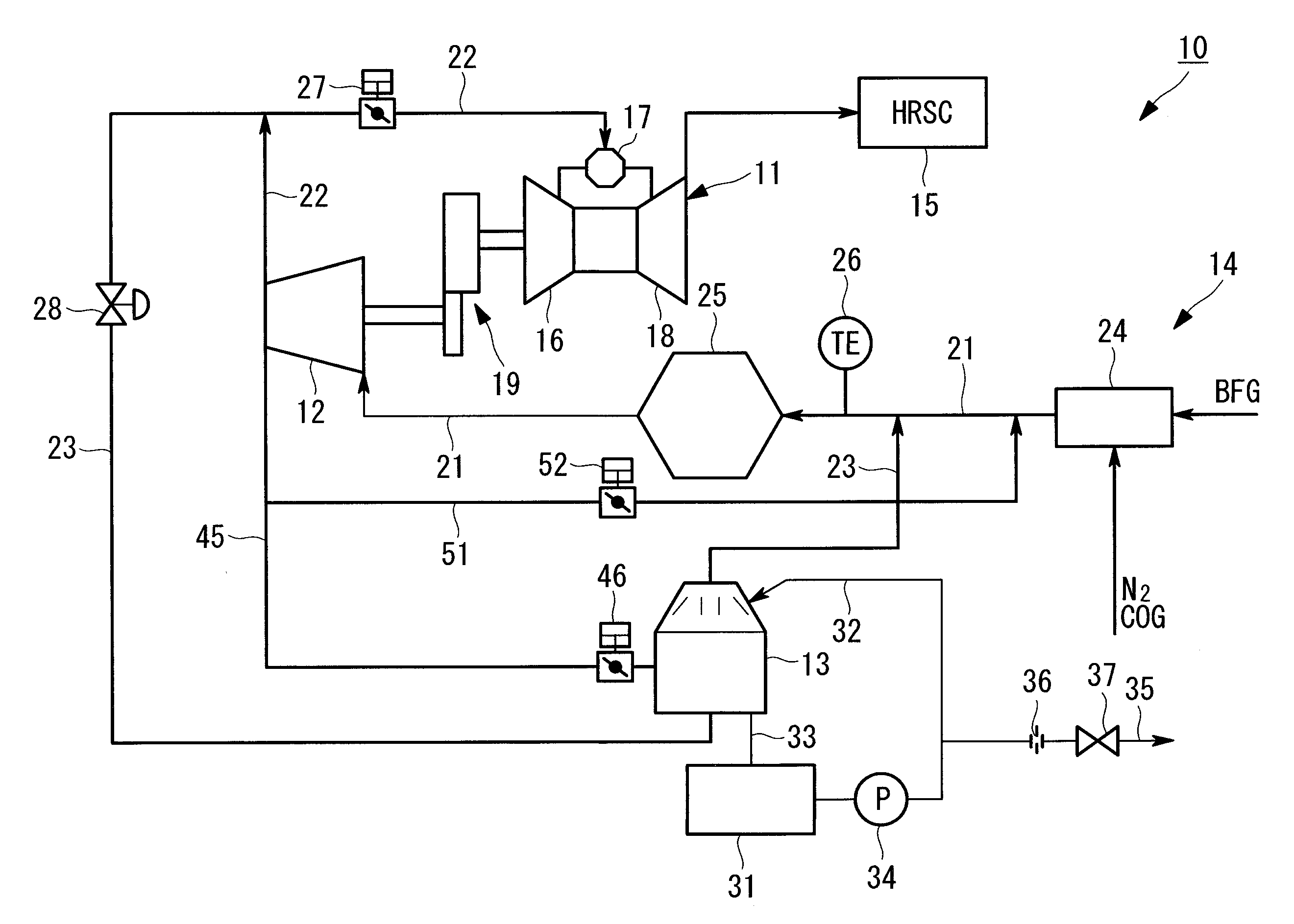
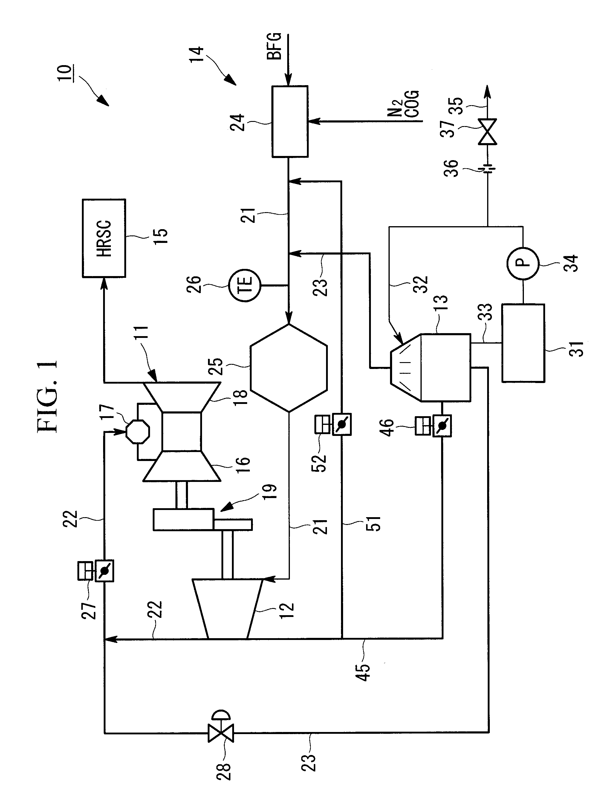
[0021]A power plant according to an embodiment of the present invention will be described below with reference to FIGS. 1 and 2.

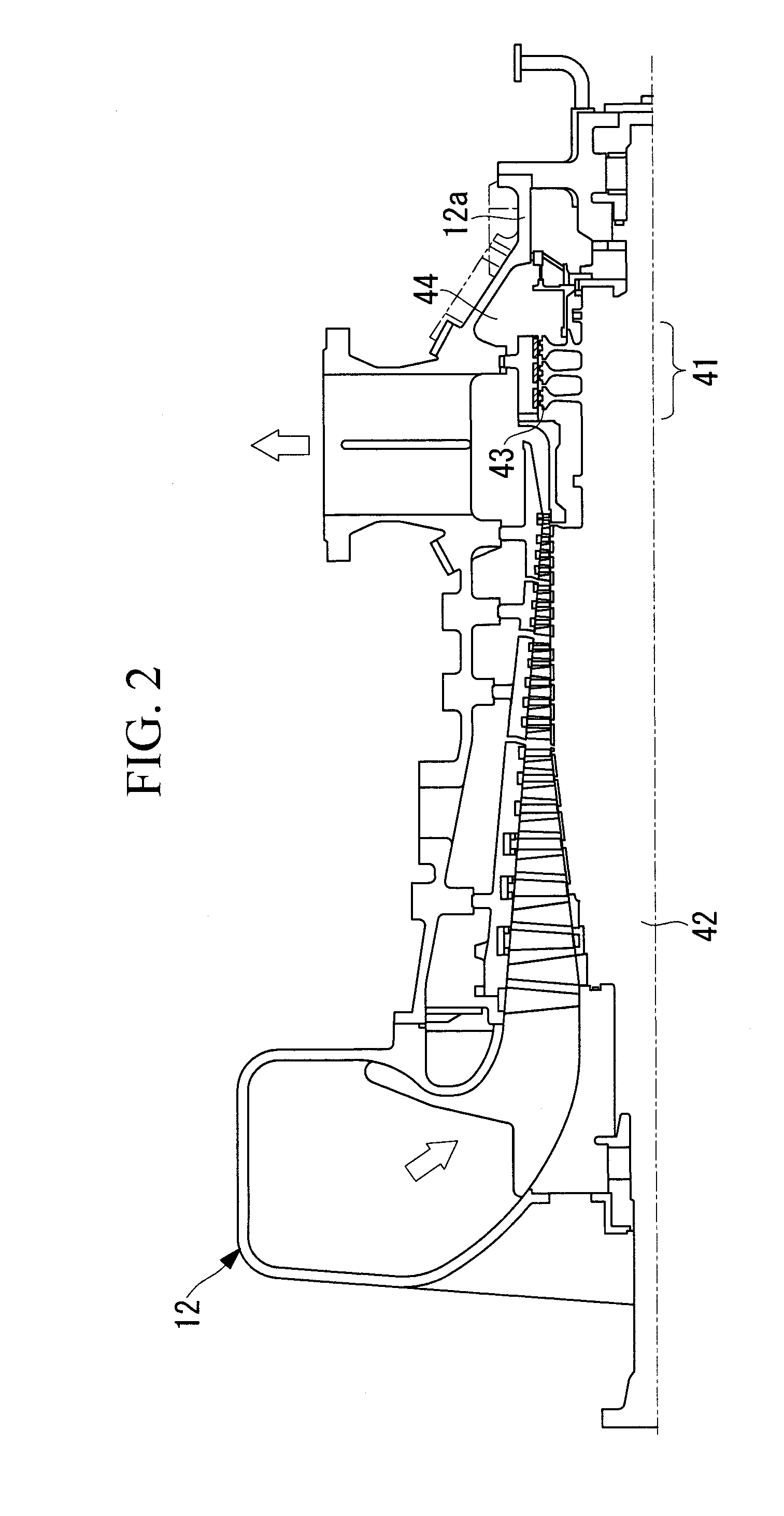
[0022]FIG. 1 is a schematic structural diagram of a power plant according to this embodiment, and FIG. 2 is a cross-sectional diagram of the BFG compressor shown in FIG. 1.

[0023]As shown in FIG. 1, a power plant 10 according to this embodiment is provided with a gas turbine 11, a BFG compressor (fuel gas compressor) 12, a generator (not shown), a fuel gas cooler (hereinafter referred to as “gas cooler”) 13, a BFG (blast furnace gas) supply system 14, a COG (coke-oven gas) supply system (not shown), and an HRSG (exhaust heat recovery boiler) 15.

[0024]The gas turbine 11 is provided with an air compressor 16, a (gas turbine) combustor 17, and a turbine 18. In addition, the gas turbine 11, the BFG compressor 12, and the generator are connected via a speed-reduction mechanism 19, and the BFG compressor 12 and the generator are configured to rotate co-operatively...


PUM


Abstract

Provided is a power plant including a gas turbine that uses a fuel gas as a fuel; a fuel gas cooler that cools the fuel gas, which is to be pressurized in a fuel gas compressor and re-circulated, using cooling water; and a dust collection device that separates/removes impurities from the fuel gas that is to be guided to the fuel gas compressor; wherein the power plant further includes heating means that heats the fuel gas that is to be guided to the dust collection device using the fuel gas that has been used to generate an anti-thrust force acting on a rotor of the fuel gas compressor.

Description

CROSS REFERENCE TO RELATED APPLICATIONS[0001]This application claims benefit of Japanese Application No. 2010-270615 filed in Japan on Dec. 3, 2010, the contents of which are hereby incorporated by its reference.BACKGROUND OF THE INVENTION[0002]1. Field of the Invention[0003]The present invention relates to a power plant provided with a gas turbine, which uses a low-heating-value gas, such as blast furnace gas (BFG), as a fuel, and a fuel gas cooler that cools fuel gas pressurized in a fuel gas compressor and re-circulated.[0004]2. Description of Related Art[0005]Known power plants provided with a gas turbine, which uses a low-heating-value gas, such as blast furnace gas (BFG), as a fuel, and a fuel gas cooler that cools fuel gas pressurized in a fuel gas compressor and re-circulated include, for example, that disclosed in FIG. 1 in Japanese Unexamined Patent Application, Publication No. Hei 9-79046.[0006]In the case where the power plant disclosed in FIG. 1 of the above-mentioned J...

Claims


Application Information

Patent Timeline
Patent Type & Authority Applications(United States)
IPC IPC(8): F02C7/224F02C3/20
CPCF02C3/20F02C7/22F05D2260/15F05D2220/75F02C7/224F01D25/00F02C6/00
Inventor TANABE, HIROSHIANZAWA, EIKI
Owner MITSUBISHI POWER LTD
Why Eureka
Try Eureka