Power Amplifier System with a Current Bias Signal Path

a power amplifier and signal path technology, applied in the direction of amplifiers, amplifiers with semiconductor devices only, amplifiers, etc., can solve the problems of high-power, around or over one watt, amplifiers (pas) in general, and high-frequency, around or over one giga hertz, etc., and achieve the effect of not being able to use high impedance lines between ic b>110/b> and ic b>120/b>

Active Publication Date: 2012-06-07
QORVO INT PTE LTD
View PDF5 Cites 20 Cited by
  • Summary
  • Abstract
  • Description
  • Claims
  • Application Information

AI Technical Summary

Problems solved by technology

Biasing of high-power, e.g., around or over one watt, amplifiers (PAs) in general, and high-frequency, e.g., around or over one giga Hertz, PAs in particular, is a more complex and challenging problem.
The fact that shipping RF signal between IC 110 and IC 120 is hard to

Method used


Image

  • Power Amplifier System with a Current Bias Signal Path
  • Power Amplifier System with a Current Bias Signal Path
  • Power Amplifier System with a Current Bias Signal Path

Examples


Embodiment Construction

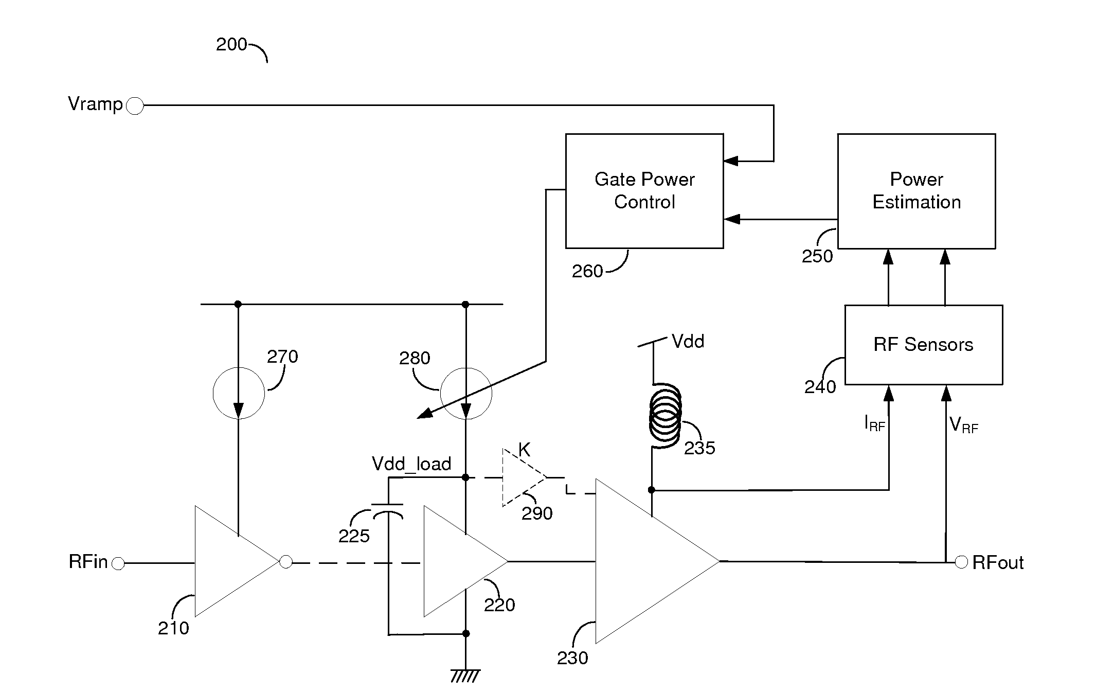
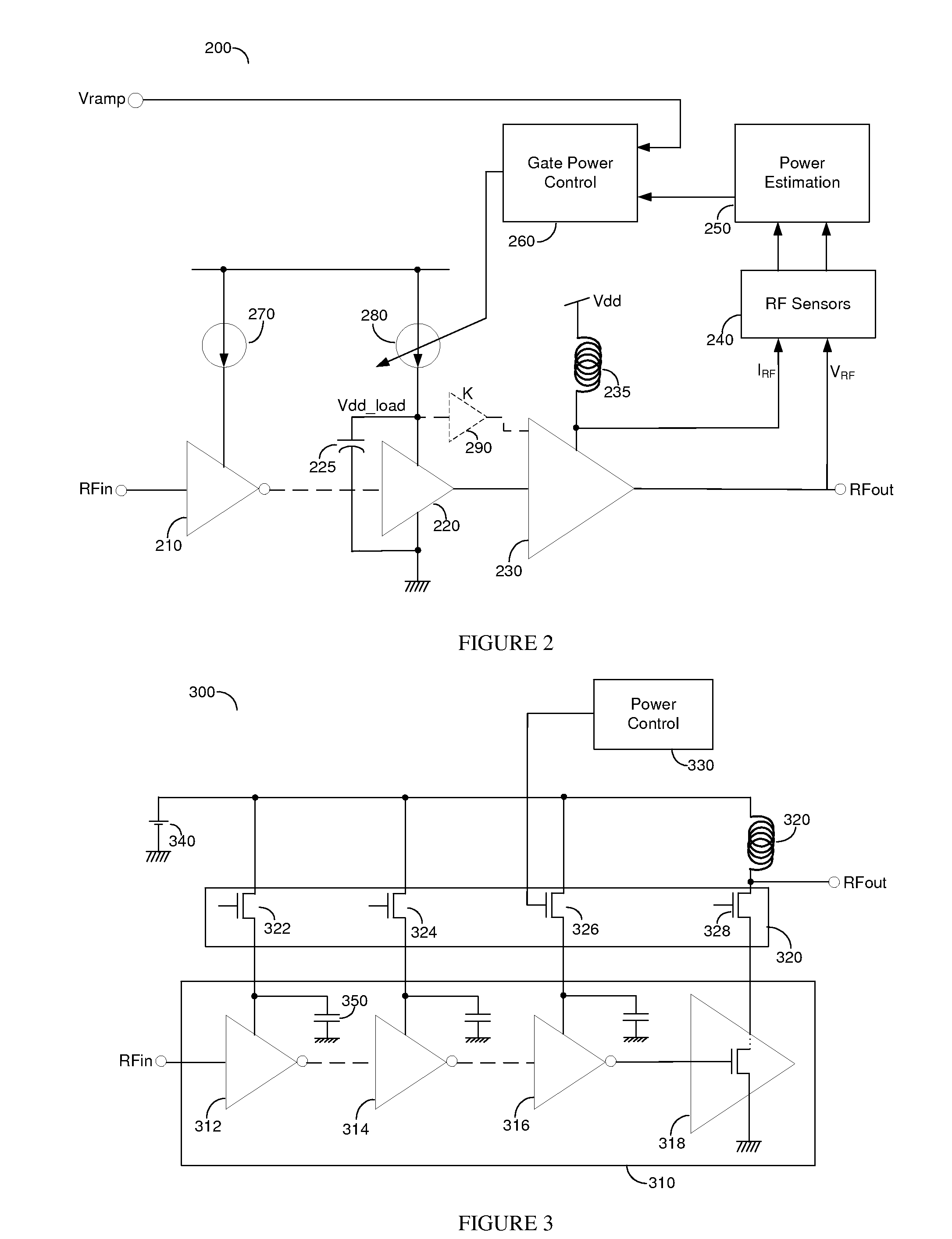
[0026]Power amplifier (PA) systems are typically comprised of a signal path integrated circuit (IC) and a power control IC. Advanced CMOS technologies may allow smart integration of such ICs into a single IC and provide an opportunity to improve performance and cost. Specifically, the radio frequency (RF) signal path is designed to enable local biasing of the gain stages that comprise the RF signal path. By using current-mode biasing instead of the prior art voltage-mode biasing significant area reduction is achieved as well as better isolation between the stages which reduces noise, and improves stability.

[0027]FIG. 2 is an exemplary and non-limiting schematic diagram 200 of a gate-power control enabling technique for current-mode biasing of the PA signal path stages. One of its advantages is that this circuit may be implemented in complementary metal-oxide semiconductor (CMOS) technology that lends itself for the integration of the RF signal path as well as the power control circu...


PUM


Abstract

Power amplifier (PA) systems are typically comprised of a signal path integrated circuit (IC) and a power control IC. Advanced CMOS technologies may allow smart integration of such ICs into a single IC and provide an opportunity to improve performance and cost. Specifically, the radio frequency (RF) signal path is designed to enable local biasing of the gain stages that comprise the RF signal path. By using current-mode biasing instead of the prior art voltage-mode biasing significant area reduction is achieved as well as better isolation between the stages which reduces noise, and improves stability.

Description

CROSS-REFERENCE TO RELATED APPLICATIONS[0001]This application claims the benefit of U.S. Provisional Patent Application No. 61 / 419,849 filed Dec. 5, 2010.BACKGROUND OF THE INVENTION[0002]1. Field of the Invention[0003]The invention relates to the design of integrated circuit (IC) power amplifier systems and more particularly the biasing of the signal path of IC power amplifier systems.[0004]2. Prior Art[0005]Design of amplifiers for various frequency ranges (low, mid, high and radio frequency) using various semiconductor processing technologies (bipolar, CMOS, GaAs, etc.) and in different configurations (single-ended, differential, quadrature, common source, common emitter, common gate, common base, etc.) is well documented in the art. In the art there are described three ways of biasing an amplifier stage: voltage bias, current bias and a hybrid technique using both voltages and currents.[0006]Biasing of low and moderate power amplifiers is relatively straightforward and can be don...

Claims


Application Information

Patent Timeline
IPC IPC(8): H03F3/04H03G3/30
CPCH03G3/3042H03F1/0233H03F1/0261H03F2200/465H03F3/245H03F2200/18H03F2200/405H03F1/223
Inventor SCOTT, BAKERMAXIM, GEORGE
Owner QORVO INT PTE LTD
Why Eureka
Try Eureka