Methods and systems for recovery of co2 gas in cement-manufacturing facilities, and processes for manufacturing cement
- Summary
- Abstract
- Description
- Claims
- Application Information
AI Technical Summary
Benefits of technology
Problems solved by technology
Method used
Image

Examples
first embodiment
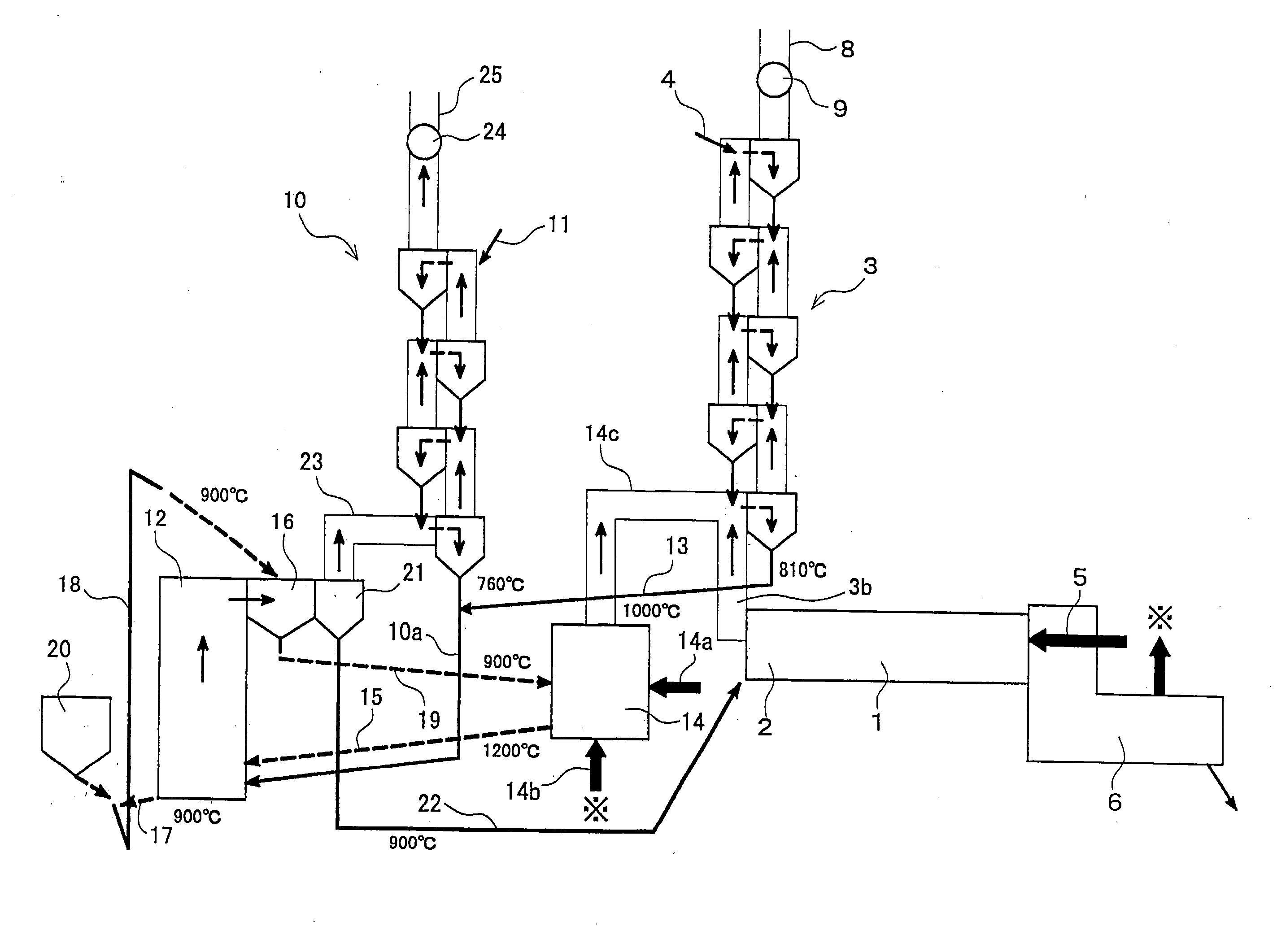
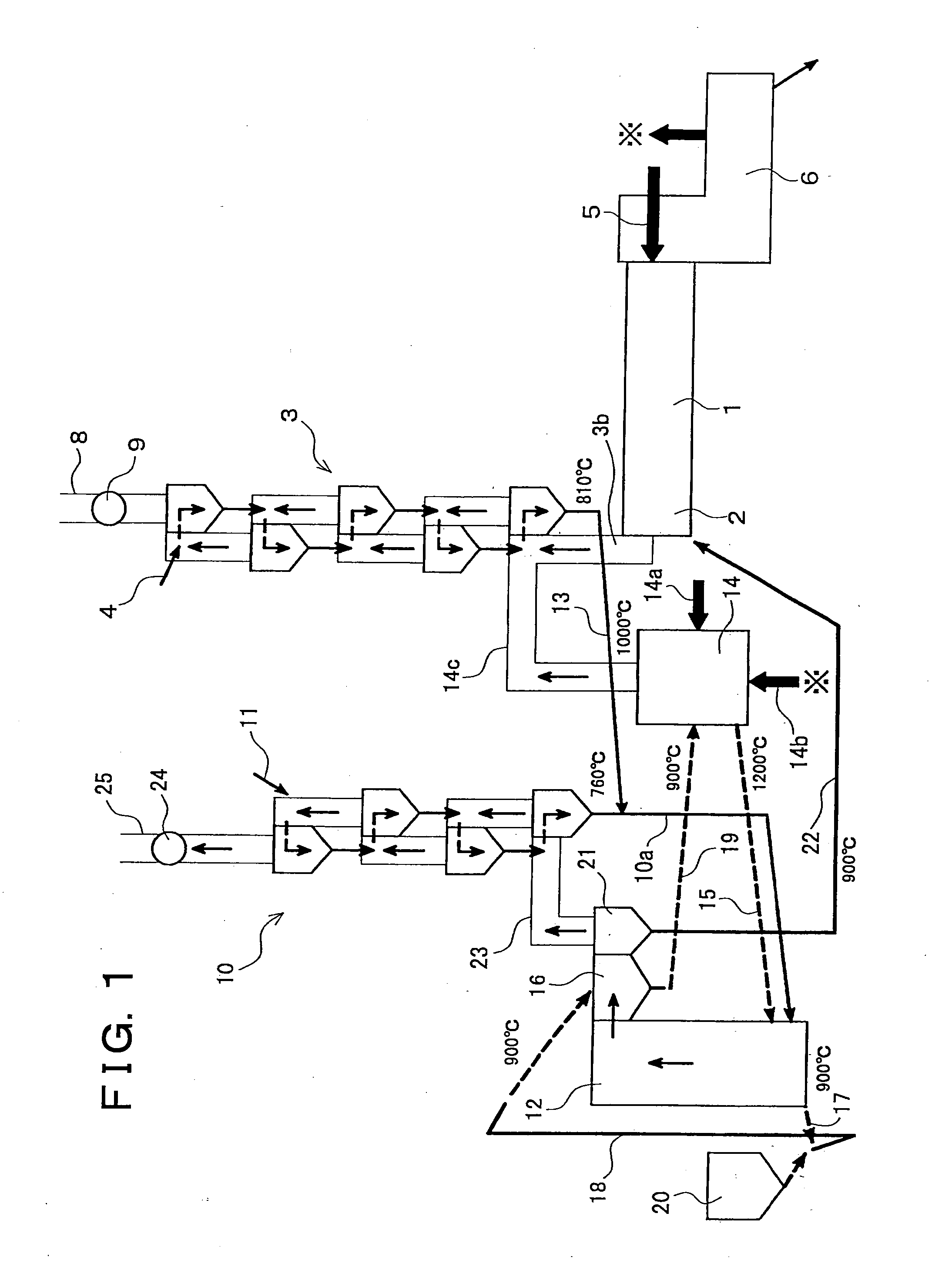
[0118]FIG. 1 illustrates a first embodiment of systems for recovering CO2 gas in cement-manufacturing facilities according to the present invention, and the first embodiment has the same structure concerning the cement-manufacturing facility as that in FIG. 16. Accordingly, the same portions are denoted by the same reference numerals, and the description thereof will be simplified.
[0119]In FIG. 1, reference numeral 10 denotes a second preheater which is provided independently from the preheater (first preheater) 3 in the cement-manufacturing facility.
[0120]This second preheater 10 is constituted by a plurality of stages of cyclones which are serially arranged in a vertical direction similarly to the above described preheater 3, and is constituted so that the cement material is fed to the cyclone in the uppermost stage from a feed line 11. The upper end of a transfer pipe 10a is connected to the bottom part of the cyclone in the lowermost stage of the second preheater 10, and the low...
second embodiment
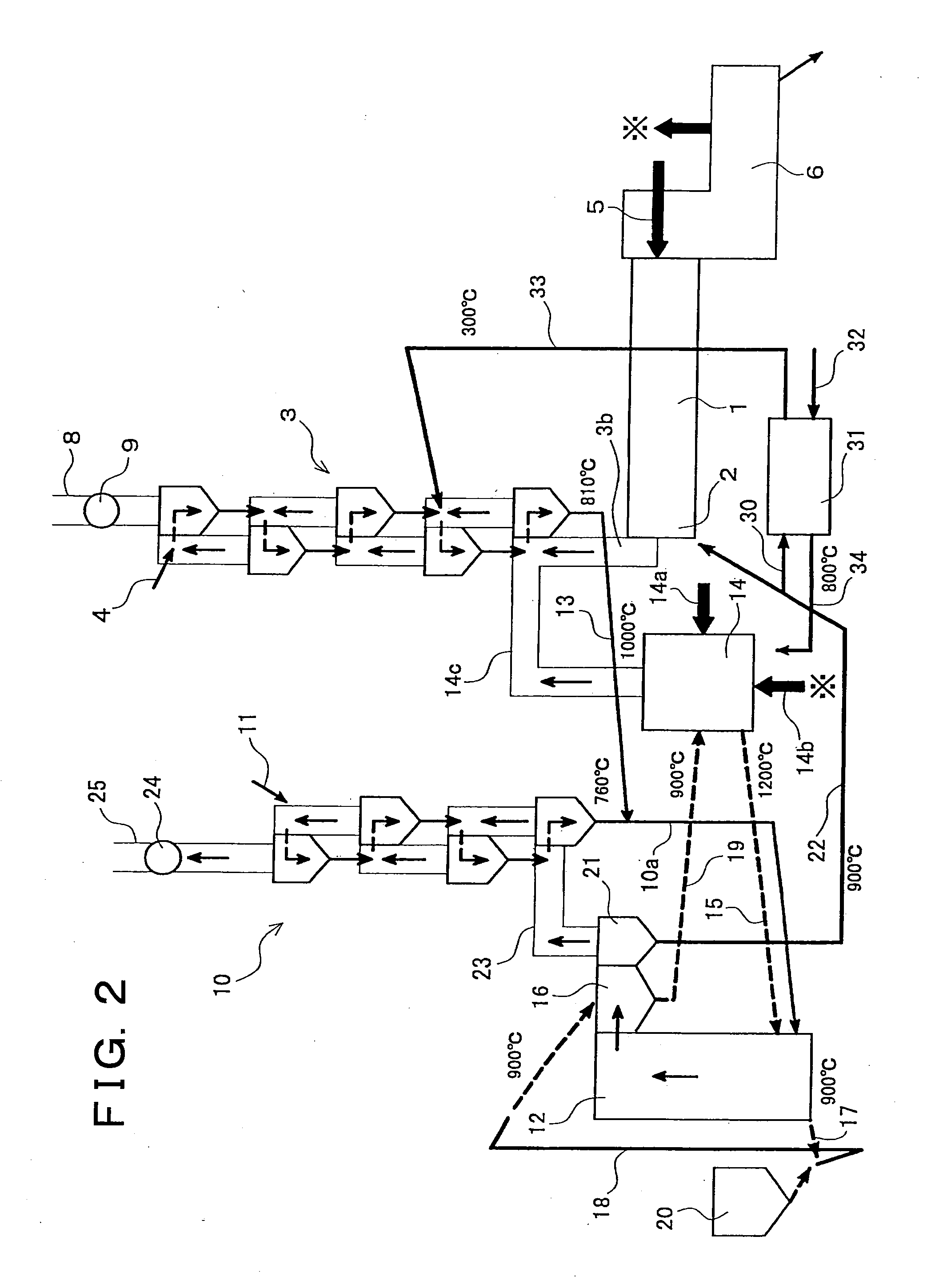
[0137]FIG. 2 illustrates a second embodiment of the systems for recovering the CO2 gas according to the present invention. The same components as those illustrated in FIG. 1 are denoted by the same reference numerals, and the descriptions will be simplified.
[0138]In this recovery system, a branch pipe 30 for branching one part of the above described cement material is provided in a return line 22 through which the calcined cement material is returned from a cyclone 21 to a kiln inlet part 2 of a rotary kiln 1. This branch pipe 30 is introduced to a heat exchanger 31.
[0139]This heat exchanger 31 is a device for heating an air which is sent from a feed pipe 32 for air, with the above described high-temperature (for instance, approximately 900° C.) cement material which is sent from the branch pipe 30, and a transfer line 33 for returning the cement material having the lowered temperature (for instance, approximately 300° C.) to the first preheater 3 is connected to the outlet side of ...
third embodiment
[0145]FIG. 7 illustrates a third embodiment of systems for recovering the CO2 gas n in cement-manufacturing facilities according to the present invention, and the third embodiment has the same structure concerning the cement-manufacturing facility as that in FIG. 16. Accordingly, the same portions are denoted by the same reference numerals, and the description thereof will be simplified.
[0146]In FIG. 7, reference numeral 10 denotes a second preheater 10 which is provided independently from the preheater (first preheater) 3 in the cement manufacturing facility.
[0147]This second preheater 10 is constituted by a plurality of stages of cyclones which are serially arranged in a vertical direction similarly to the above described first preheater 3, and is constituted so that a cement material before calcination (uncalcined cement material) k is fed to the cyclone in the uppermost stage from a feed line 111. The upper end of a transfer pipe 10a is connected to the bottom part of the cyclon...
PUM
| Property | Measurement | Unit |
|---|---|---|
| Fraction | aaaaa | aaaaa |
| Temperature | aaaaa | aaaaa |
| Concentration | aaaaa | aaaaa |
Abstract
Description
Claims
Application Information
 - R&D Engineer
- R&D Manager
- IP Professional
- Industry Leading Data Capabilities
- Powerful AI technology
- Patent DNA Extraction
Browse by: Latest US Patents, China's latest patents, Technical Efficacy Thesaurus, Application Domain, Technology Topic.
© 2024 PatSnap. All rights reserved.Legal|Privacy policy|Modern Slavery Act Transparency Statement|Sitemap